Sections of Loft |
  
|
The operation is always defined beginning with selecting the sections. For successful operation creation, at least two sections are required. Any system object may be used as a section that contains wire or surface geometry.

General information when defining sections
The elements selected as sections are highlighted in green by default. The active section is highlighted in red. Active considered the section that is being currently manipulated. For example, working on a section composition makes it active. Settings of the highlighting colors are done in the system options dialog box.
When you select each section, a starting point is assigned, highlighted in blue. The set of starting points forms the first match sequence. When working with closed sections, the starting point is assigned at the vertex of the section contour closest to the cursor. When using open sections, the starting point is assigned at the closest end of the wire. If the variant of section synchronization proposed by the system is not suitable, then the starting sequence can be changed or new matches can be added.
|
1. First section (Active) 2. Second section 4. Second section bypass direction 5. Start match 6. Section matching starting points |
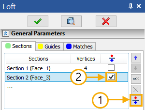
In each section, an arrow is drawn from the starting point, showing the direction of the contour direction. To successfully create an operation, it is necessary to achieve the same direction in all sections. You can change the contour bypass direction using the Reverse option.
When using closed or open contours, the system tries to establish the synchronization of the bypass directions using Autoreverse. If you want to use the Reverse option, you must first disable the Autoreverse option.

Switching the option for open contour moves the starting point to the opposite end of the contour.
After starting the operation, the Sections tab is automatically activated and the user will be prompted to select sections.
One 3D profile (single/multi-contour, closed/open, planar/non-planar), one 3D path (closed/open), one face, one point or set of edges can be selected, which must form one continuous contour.
|
|
1. Open 3D Path 2. Closed 3D Profile 3. Set of Edges |
5. Non-planar 3D Profile 6. 3D Node 7. Closed 3D Profile |
All available selection filters are displayed in the filter toolbar.
![]()
On the left side of the filter toolbar, a selection of advanced filters is available, such as Edge Midpoint, Center of curve/edge, Profile bounds, etc.
The following automenu option is active by default:
|
<S> |
Automatic contour search |
While it's active, the system automatically decides whether selected element should be included into one of existing sections or a new section should be added. If selected non-closed element touches one of the existing non-closed sections, such element is included into such section; otherwise a new section is added.
Upon disabling the ![]() option, each selected element will be added to the end of the section list as a new section. Sections can be moved up and down the list using the corresponding buttons of the parameters window.
option, each selected element will be added to the end of the section list as a new section. Sections can be moved up and down the list using the corresponding buttons of the parameters window.
The first and last sections cannot be moved in the list if they are points.
To remove any object from the list, after selecting an object in the list, press the Delete Section.
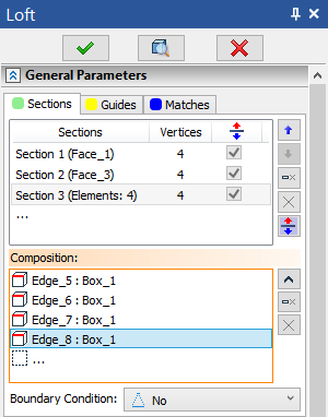
All selected objects go to the Composition field. This field displays a list of the names of the selected elements for each specific section. To replenish the composition of the section, you need to expand the drop-down list of the Composition field, after which you can start selecting additional objects.

The number of elements in the Composition field is displayed opposite the selected section.
A section can only be composed of objects containing geometry of the same type.
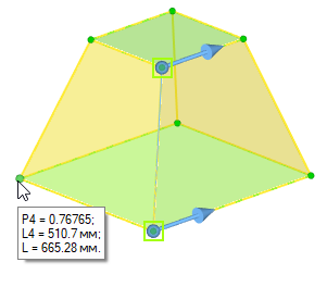
For sections, there are special manipulators at the original vertices, when you hover over which, additional information about the parameter and length from the starting point, as well as the entire length of the section, is displayed.

Р(i) – vertex parameter. The range is [0, 1].
L(i) – length in document units
i – vertex indices (starting at 1).
The length and parameter are measured from the starting point.
L – the entire length of the section.
Rounding to 5 decimal places.
Pi = Li / L;
Defining boundary conditions for sections is described in the Boundary Condition section.