Outline |
  
|
Calling the command:
Icon |
Ribbon |
|
Support Geometry > 3D Path > Outline |
Keyboard |
Textual Menu |
<3KCO> |
|
Automenu of the |
|
<O> |
Outline |
Creating a 3D path as an outline edge can be found useful for defining the separation line when designing diecast molds.
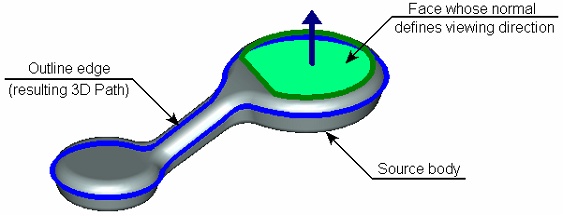
Construction of a body's outline edge can be schematically described as follows: imagine that spatial lines are drawn parallel to the viewing direction through each point on the body's surface. The points on the body surface in which such a line just touches the body (without intersecting it) are the candidate points for an outline edge.
To create a 3D path, the source body and the viewing direction are specified. The system analyzes the surface of the body, searching for points satisfying the outline edge definition. The resulting set of points is united in one curve – the 3D path.

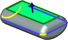
If it is impossible to join all found points into one curve, the system returns a set of separate outline edge segments. The user is offered to select the segment that will be used for building the resulting 3D path. One can select multiple outline edge segments simultaneously. In this case, multiple 3D path will be created rather than a single one, according to the number of selected segments.

Viewing direction is defined by normal to upper face System-identified outline edge segments are shown as yellow and blue lines.
A situation as possible when the vector of the viewing direction is parallel to some of the body's faces. In this case, all points of such face satisfy the definition of the outline edge, that is, the system finds an outline "surface" instead of an edge. This situation is resolved by the system by constructing the outline edge through the first points encountered on such face. As a result, most often, the outline edge is constructed along one of the side edges of such a face. A better shape of the outline edge will be obtained by applying the "vertical" face processing. In this mode, the system draws the outline edge straight across the face.
|
|
Constructing outline edge without "vertical" face processing |
Constructing outline edge with "vertical" face processing |
The mode of processing Vertical faces is turned on in the command’s parameters window.
The mode of processing Vertical” faces is turned on in the command’s parameters window.
The body whose outline edge will be constructed is selected by the option:
|
<1> |
Select Solid Body |
The viewing direction is defined either by two 3D points or by one 3D element suitable for defining a vector:
|
<2> |
Select First point of Direction |
|
<3> |
Select Second point of Direction |
|
<4> |
Select direction |
After specifying the source body and the viewing direction, the image of the created outline edge will be shown in the 3D scene.
In the case when the system cannot create a single outline edge, the 3D scene will show one of the identified outline edge segments. To create a 3D path based on it, simply confirm the path creation by ![]() .
.
The full list of found outline edge segments is displayed in the command’s parameters window. To create a 3D path based on another outline edge segment, it is possible to select the desired segment in the parameters window or use the additional option:
|
<Tab> |
Change Outline |
This option allows us to loop through the outline edge segments found by the system (when pressing this option the next segment of the outline edge is displayed on the screen). The segment selected in the list is displayed with a light blue color in 3D scene.
To create a 3D path by several segments of the outline edge, it is necessary to find all desired segments in the list and checkmark them, and then confirm the path creation with the help of ![]() .
.