Parametric Change of 3D Node Position |
  
|
Calling the command:
Icon |
Ribbon |
|
Support Geometry > 3D Path > Parametric Change of 3D Node Position |
Keyboard |
Textual Menu |
<3KPP> |
|
Automenu of the |
|
<A> |
Parametric Change of 3D Node Position |
The way of creating a 3D path by parametric variation of a 3D point is used for creating trajectories of complex geometry.
A spatial curve of the path results from "sweeping" a 3D point along an arbitrary or specifically defined spatial trajectory. "Sweeping" of the point is realized by multiple copying of the source 3D point. The resulting set of points is joined by a spline, and a 3D path is built. The resulting 3D path can be closed.
When constructing such path, a general mechanism is used that provides the final result based on parametric copying of the source element. This mechanism is used in the By Parameters operation – when creating a body based on "sweeping" (copying) a profile. It is also used in the Parametric Array operation, where the result of the operation is a set of parametrically varying copies of the source object.
This algorithm is described in most details in the By Parameters chapter. The current chapter provides only a brief description and some examples of using this mechanism.
To create a 3D path by a parametrically varying point, you need to define the law, according to which the copies of the source 3D point will be constructed.
A so-called current copy's coordinate system is calculated for each copy of the point. Copying the 3D point is done in the direction from the source coordinate system to the calculated target coordinate system of the current copy. The user can select one of the local coordinate systems available in the model as the source coordinates. If no local coordinate system is selected, then the source coordinate system will be either the global coordinate system or the coordinate system of the first copy, depending on the method of calculating the current copy's coordinate system.
The current copy's coordinate system (that is, its origin and axes orientation) can be defined by one of two methods:
•Free copy orientation. The laws of modifying the coordinate system parameters of the current copy of the 3D point are described by expressions.
•Copy orientation by 3D curves or surfaces. To define the spatial position of the current copy's coordinate system, existing 3D curves or surfaces of other bodies are used. By directing the copy's coordinate system, the user controls the position of each copy of the 3D point.
Directing the copy's coordinate system is done via the operation parameters. There are parameters of two types - driven parameters and driving parameters.
Driven parameters are the parameters whose values are calculated automatically in the process of creating a copy of the point. You can assign independent variables to read the values of such a parameter.
Driving parameters are the entries with the dependencies defined by the user. The entries of the driving variables allow entering arbitrary expressions that can include any system variable. For example, by including a variable representing the ID number of the 3D point's copy in such an expression will make the value of this parameter dependent on the copy number.
Some operation parameters can be sometimes driving, and sometimes driven. The leading parameter Copy number is always driven. It necessarily requires an independent variable that would be assigned the current value of the copy number while calculating the operation. The copy number automatically changes during the calculation from 1 up to the specified amount with increment of 1.
Calculation is done in the following order: first, the copy number is incremented, then the driving parameters are calculated, after which the rest of driven parameters are calculated (if any), and, finally, copying is done. All copies of the 3D point obtained in this way are united in one spline.
Upon calling the command following actions become available:
|
<R> |
Select 3D Node |
|
<1> |
Select Curve defining position of coordinate system |
|
<2> |
Select 3D Curve defining X direction of coordinate system |
|
<3> |
Select 3D Curve defining Y direction of coordinate system |
|
<4> |
Select Surface defining X direction of coordinate system |
|
<5> |
Select Surface defining Y direction of coordinate system |
|
<6> |
Select source LCS |
|
<7> |
Cancel selection of elements defining coordinate system |
As was mentioned earlier, one can distinguish two ways of creating a path by parametric variation of a 3D point. Let's review examples of each of them.
Free copy orientation method
When creating a path by this method, all that is required is selecting a 3D node, specifying the number of copies and assigning an independent variable to the Copy number parameter. By using the variable assuming the value of the current copy number, one can create certain dependencies in the driving the variable entries, as well as in 2D or 3D constructions, that, in turn, define the position of the source 3D point.
Example 1
Let's review the use of a parametric path on the example of creating a model of a cam. This example can be found in the Examples library, the folder 3D Modeling/Paths/Cam.grb. The source data is represented by a graph defining the cam surface.
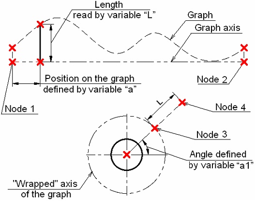
A parametric segment is constructed between the nodes 1 and 2. Its position is defined by the value of the variable "a" in the range from 0 to 1, inclusive. As the variable "a" changes, the line will move from point 1 to point 2. The resulting line will cost the axis of the graph and the graph curve. A segment can be constructed between these points. Its length will be equal to the current value of the function represented by the graph. The read value of the segment length is stored in the variable "L" (by means of the function get).
To construct a 3D Path repeating the contour of the cam surface, one needs to create such a 3D node that will change its spatial position according to the law defined by the graph as the variable changes that is assigned to be the copy counter. Such a node can be conveniently created by adding a few additional 2D constructions based on already available data.
To get the cam of the desired size, the axis of the graph needs to be "wrapped" onto a circle of the specified radius. In the given example, the constructed circle has the radius of 50 mm. A new line needs to be created through the circle center at an angle to the horizontal. The variable "a1" shall be assigned to the parameter defining the slant angle of this line.
The node 3 is constructed at the intersection of the circle and the slanted line. The node 4 is constructed at the distance "L" from the node 3 along the slanted line. A 3D node is constructed based on the 2D node 4. For that purpose, a "Front view" workplane was created on an existing page.
Now, we need to relate all variables in such a way that the 3D node would rebuild according to the copy counter changes. This can be achieved by introducing the following expressions instead of fixed values of some variables, that will maintain the dependency from the copy number:
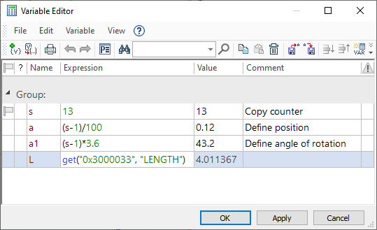
Since the values of the Copy number parameter always start from one, sometimes a (–1) adjustment is necessary in the expressions employing the Copy number variable.
At this point, the parametric 3D path can be constructed. We need to define two parameters in the parameters dialog: enter the number of copies and assign the variable to act as the copy counter. In the given example, the "Copy number" parameter is assigned the variable "s".


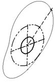
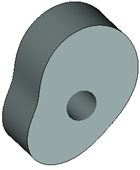
The first copy of the 3D node will coincide in its position with the 101-th. As a result, a closed 3D path will be created. Its geometry will correspond to the cam shape. Next, to create the cam body, extrude the path in the normal direction by 50 units and create a solid body based on the obtained sheet surface using Sew operation. Finally, one can make a cylindrical hole along the cam's axis (by extruding a circle with automatic subtraction from the main body).
Method of orienting copy by paths or surfaces
The method of orienting a copy by paths or surfaces is convenient when other means fail that would define the law of varying copy parameters by expressions. In such cases, it could be convenient to use various 3D curves or surfaces for defining the position and orientation of the current copy's coordinate system.
Example 2
As an example of using a parametric 3D path with orientation of the copy by paths or surfaces, let's consider building a 3D path defining the outer border of a "waves" surface. On the figure, it is denoted as 3D path 2. To construct such a path, we need:
•the source 3D node whose position will be changing depending on the number of the copy being created in the process of building the path;
•a 3D path defining the position of the coordinate system origin for each copy;
•a surface, defining the orientation of the X-axis of each copy's coordinate system.
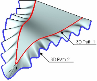
The path being created shall repeat the shape of the outer border of the source sheet body. Therefore, to define the origins of the copies' coordinate systems, we would need to use a 3D path built on the edges of the source sheet body – the 3D path 1.
An auxiliary workplane is constructed in order to get the source 3D node, which is perpendicular to the 3D path 1 and is passing through one of the vertices of the source sheet body. The necessary 2D constructions are created on the workplane. The sought 3D node is created based on a 2D node on the workplane – the Node 2. Node 2 was constructed as follows: first, the Node 1 was created on the workplane with the coordinates (0,0) (corresponding to the vertex of the source sheet body through which the workplane passes). A horizontal line is drawn through this node. A vertical line is drawn at the distance "y" from Node 1, perpendicular to the horizontal line. Node 2 lies on this line at the distance "L" from the lines intersection point. The value of the "L" variable is defined in such a way as to vary with the changes in the copy counter of the 3D path. Therefore, as the 3D path creation progresses, the position of the 2D Node 2 changes by the sinusoidal law with the current copy number, and so does the based on it 3D node.
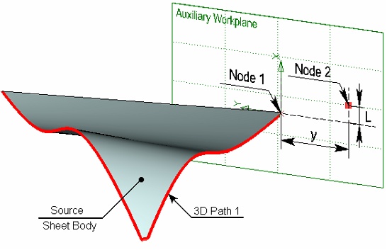

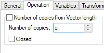
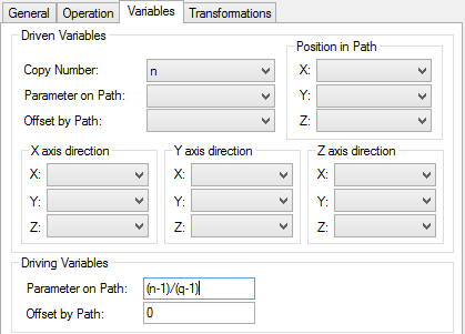
To define orientation of the X-axis of the copies' coordinate systems with the progress of the parametric path creation, we need to specify the source sheet body itself. If no surface is selected, then the axis orientation will be defined based on the curvature vector of the 3D path 1, whose direction may change abruptly. The following needs to be defined in the path parameters dialog: the number of copies (the variable "q"), the copy counter variable (in the given example, this is the variable "n") and the driving parameter "Parameter along path". Once 3D path 2 is created, the based on it "waves" surface can be created by Loft operation.
This example is located in the library Examples, the folder 3D Modeling/Path/Parametric path with copies orientation by path and surface.grb.