3D Path on Intersection of Elements |
  
|
Calling the command:
Icon |
Ribbon |
|
Support Geometry > 3D Path > 3D Path on Intersection of Elements |
Keyboard |
Textual Menu |
<3KPG> |
|
Automenu of the |
|
<B> |
Intersection of Elements |
This way enables users to create 3D path at the intersections of elements. Sheet objects (workplanes, worksurfaces, faces and sheet bodies) as well as solid bodies can be used as intersection elements.
The first element can only be set by one object, the second one – by a set of objects.
In case there are several sections formed in the intersection, you can determine the ones by which 3D paths will be built.
|
|
Open-loop sections are formed as a result of several objects intersection. If a solid body is used as one of the intersecting elements, the obtained adjacent sections are automatically combined into one. If several solid bodies intersect, the resulting contours formed by adjacent sections will be closed.
When creating a 3D path at element intersection with the use of sheet objects, sometimes it is necessary to consider one of the intersection elements without taking into account its limiting contours, both external and internal (i.e. the sheet object is considered an infinite surface). It enables users to create a 3D path only limited with the second element contours.
|
|
Taking into account limiting contours |
Without taking into account limiting contours |
Upon calling the command, options for choosing objects as intersecting elements appear in the automenu:
|
<A> |
To choose the first element |
|
<S> |
To choose the second element |
The following automenu option cancels selection of all the elements:
|
<F> |
To cancel selection of all the elements |
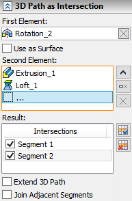
The selected elements are shown in the corresponding fields in the command parameters window. To control the list of the objects selected as the second element, Expand ![]() , Collapse
, Collapse ![]() , Delete Element from the List
, Delete Element from the List ![]() , Clear
, Clear ![]() buttons are used.
buttons are used.
Set the flag Use as Surface to use a sheet object selected as the first element without taking into account its contours.
Resulting sections obtained after elements intersection are shown in Result field. The flag set indicates creating a 3D path at this section after confirming the command. You can set on and off all the flags at the same time using Select All ![]() , Clear
, Clear ![]() buttons.
buttons.

Extend 3D Path parameter enables users to expand the resulting section up to the first element boundaries.
In case the first element is used as a surface, the resulting sections will possess an infinite length when enabling this parameter.
Join Adjacent Segments parameter is used for combining resulting adjacent segments when several sheet objects intersect.