Sew |
  
|
Calling the command:
Icon |
Ribbon |
|---|---|
|
3D Model > Special > Surfaces > Sew Surfaces > Operations > Sew |
Keyboard |
Textual Menu |
<3SS> |
Operation > Surfaces > Sew |
This command unites a set of disjoint surfaces into one surface body and, if necessary, creates a closed volume, yielding a solid body.
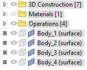
To create the operation, you need to define the set of surfaces to sew. You can select 3D profiles, faces or operations as the original surfaces. In the latter case, the operation must be a surface body, for example, the result of extruding or rotating a wire contour, or an import surface from other applications. Upon sewing, original surface bodies can be either kept, or replaced by the result of sewing, depending on the parameters of sewing. Original 3D profiles and faces are kept anyway.
The surfaces being sewn must adjoin without overlapping.
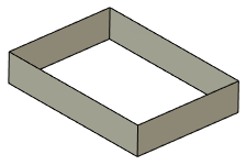
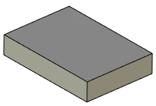
The result of sewing can be either a solid body or a surface body. By default, a solid body is created. In this case, the system attempts to create missing faces to make a closed volume.
|
|
|
Original model 1 - Surface body 2 - 3D Profiles |
Surface body created |
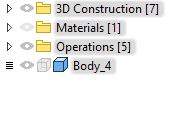
Solid body created |
In some cases (for example, when the missing surface requires more than one face), the solid body cannot be created.
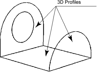
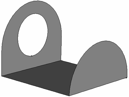
To execute the command, do the following:
1. Select surfaces to sew.
2. Specify advanced parameters (optional).
3. Confirm operation creation.
Selection of sewing surfaces
To make a sewing, you need to specify the 3D elements defining the set of surfaces to sew. This can be done with the help of the following automenu options:
|
<R> |
Select 3D Profile |
|
<F> |
Select Face |
|
<O> |
Select surface operation |
...or corresponding filters in the filter toolbar.
The selected 3D elements are entered in the Elements list in the command's parameters window. When selecting faces of some body (or several bodies), you can additionally tell the system which set of faces of this body (bodies) to sew: Only Selected or All Excluding Selected.
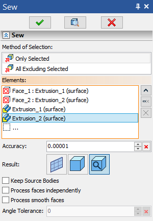
There are two ways to cancel a 3D element selection:
•Pick this element again in the 3D scene using ![]() ;
;
•Pick it in the Elements list in the command's parameters window and click Delete Element from the List.
To cancel the selection of all elements at once, use the option:
|
<K> |
Cancel selection |
Additional parameters
Accuracy
Object are considered coinciding within this tolerance. The lower the value, the lower the allowable gaps between elements to be sewn. Maximum allowed value - 0.1.
Result
This parameter defines, whether the system will try to create a solid body from the sewn surfaces by automatically generating missing faces to make a closed volume. Following options are available.
•Solid
The system will attempt to create a solid body. If this is impossible, the operation will throw an error.
•Surface
The surface body will be created from the selected elements.
•Default
The system tries to create a solid body, and if this is not possible, it creates a surface. This option is selected by default.
Keep source bodies
Upon sewing, original surface bodies can be either kept, or replaced by the result of sewing, depending on the parameters of sewing. Original 3D profiles and faces are kept anyway.
Process faces independently
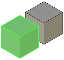
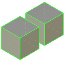
The option provides the ability to sew in one operation several separate bodies that are not in contact with each other.
Process smooth faces
If this option is disabled, selecting a face smoothly connected to other faces results in sewing the whole sequence of smoothly connected faces. However, only the directly selected face is put into the list of source elements of the Sew operation in this case. Therefore, upon further changes in the model, the set of faces to be sewn may change automatically in accordance with changes in the sequence of smoothly connected faces containing the selected face.
Alternatively, you can select a sequence of smoothly connected faces, using the ![]() Smooth Elements Selection option of the filter toolbar. In this case, all selected faces are put into the list of source elements of the Sew operation. Therefore, upon further changes in the model: if new faces will appear in the sequence, they won't be included into the sewing; if some of the initially selected faces will cease to exist, the sewing will throw an error.
Smooth Elements Selection option of the filter toolbar. In this case, all selected faces are put into the list of source elements of the Sew operation. Therefore, upon further changes in the model: if new faces will appear in the sequence, they won't be included into the sewing; if some of the initially selected faces will cease to exist, the sewing will throw an error.
Angle Tolerance
Maximum angle in radians between tangents to selected faces on junction, which allows the faces to be considered smoothly connected. Maximum allowed value - 0.1.
Topics in this section: