Parametric Array of 3D Elements |
  
|
Icon |
Ribbon |
|---|---|
|
3D Model > Operations > Array > Parametric Array Assembly (3D) > Assembly > Array > Parametric Array Sheet Metal (3D) > Advanced > Array > Parametric Array Surfaces > Advanced > Array > Parametric Array Primitives > Advanced > Array > Parametric Array Support Geometry > Copy > Array > Parametric Array |
Keyboard |
Textual Menu |
<3AA> |
Operation > Array > Parametric Array |
The command creates an array by parametric copying of s source object
Main concepts of creating a parametric array are described in the Classes of Arrays of 3D Elements section.
In order to create a parametric array, perform following steps upon calling the command:
1.Choose a type of the array to be created (![]() array of constructions,
array of constructions, ![]() array of operations,
array of operations, ![]() array of bodies);
array of bodies);
2.Select source objects of the array;
3.Select a source LCS (optional step);
4.Define a number of copies;
5.Select elements defining a coordinate system of a current copy (optional step);
6.Choose an axes direction calculation method (optional step, available if elements defining a coordinate system of a current copy were selected);
7.Select driven variables (the set of available parameters is different in free copies orientation mode and orientation of copies by curves or surfaces mode)
8.Define driving variables (the set of available parameters is different in free copies orientation mode and orientation of copies by curves or surfaces mode)
9.Define optional parameters of the array (optional step);
10.Confirm the operation (![]() in the automenu or in the header of the parameters window).
in the automenu or in the header of the parameters window).
Parametric array is formed by copying source objects from source coordinate system to coordinate system of a current copy. The global coordinate system of the current document is used as the source coordinate system by default. You can assign any LCS existing in the 3D scene as the source LCS, using the following automenu option:
|
<6> |
Select Source LCS |
It enables the filter for selecting ![]() LCSes on the filter toolbar, so you can select
LCSes on the filter toolbar, so you can select ![]() the desired LCS in the 3D scene or in the model tree. Selected LCS is highlighted in green in the 3D scene. Source LCS is not indicated in the command's parameters window.
the desired LCS in the 3D scene or in the model tree. Selected LCS is highlighted in green in the 3D scene. Source LCS is not indicated in the command's parameters window.
You can cancel the selection, using the following automenu option:
|
<7> |
Cancel selection of elements defining coordinate system |
Keep in mind, that this option also cancels the selection of elements defining a coordinate system of a current copy in the orientation of copies by curves or surfaces mode.
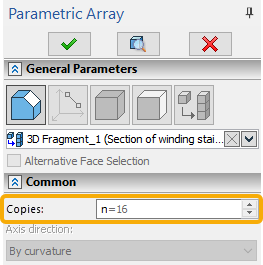
The number of Copies can be specified in the Common tab of the command's parameters window.

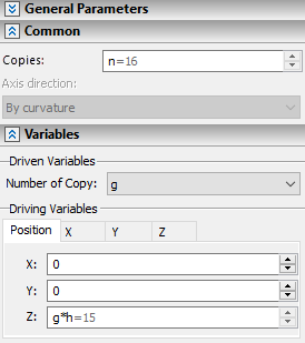
Command's parameters window have different layout depending on a copies orientation mode.
The detailed information on this mode of copy's LCS orientation and geometrical meaning of its parameters is available in the Free Instance Orientation in Parametric Sweep section.
By default, parametric arrays are created in the free copies orientation mode. Direction of copy's LCS axes in this mode is defined by user-assigned expressions for driving variables. Therefore, this mode doesn't require selecting curves or surfaces for defining copies orientation, and the Axis direction drop-down list in the Common tab of command's parameters window is inactive.
The Variables tab of command's parameters window contains two groups of parameters - Driven Variables and Driving Variables.
The Driven Variables group in this mode contains only a single parameter - number of copy. The Number of Copy drop-down list contains names of all independent numeric variables available in the current document. Selecting a name of a variable in the list makes this variable take values of number of copy.
The Driving Variables group in this mode contains three tabs:
•Position
Contains input boxes for defining X, Y, Z coordinates of current copy's LCS origin.
•X
Contains input boxes for defining X, Y, Z coordinates of a point, which defines a direction of current copy's LCS X axis.
•Y
Contains input boxes for defining X, Y, Z coordinates of a point, which defines a direction of current copy's LCS Y axis.
•Z
Contains input boxes for defining X, Y, Z coordinates of a point, which defines a direction of current copy's LCS Z axis.

Orientation of copies by curves or surfaces
The detailed information on this mode of copy's LCS orientation and geometrical meaning of its parameters is available in the Orienting Instances by Paths or Surfaces in Parametric Sweep section.
This mode is activated by selecting a curve, which defines position of current copy's LCS origin. A curve can be selected, using the following automenu option:
|
<1> |
Select Curve defining position of coordinate system |
This option enables the filter for selecting ![]() wires (
wires (![]() 3D profiles,
3D profiles, ![]() faces,
faces, ![]() edges,
edges, ![]() loops,
loops, ![]() 3D paths) on the filter toolbar, so you can select
3D paths) on the filter toolbar, so you can select ![]() the desired object in the 3D scene or in the model tree. Selected object is highlighted in green in the 3D scene. It is not indicated in the command's parameters window. Upon selecting a
the desired object in the 3D scene or in the model tree. Selected object is highlighted in green in the 3D scene. It is not indicated in the command's parameters window. Upon selecting a ![]() face, it is highlighted in blue in the 3D scene and the set of edges forming this face's boundaries is used as the curve defining position of coordinate system.
face, it is highlighted in blue in the 3D scene and the set of edges forming this face's boundaries is used as the curve defining position of coordinate system.
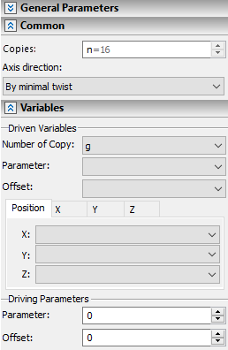
The layout of command's parameters window changes upon selecting a curve:

Optionally, current copy's LCS axes orientation can be defined either by curves or surfaces. For this purpose curves can be selected, using following automenu options:
|
<2> |
Select Curve defining X direction of coordinate system |
|
<3> |
Select Curve defining Y direction of coordinate system |
Such curves are selected in same way as a curve defining position of coordinate system.
Surfaces can be selected, using following automenu options:
|
<4> |
Select Surface defining X direction of coordinate system |
|
<5> |
Select Surface defining Y direction of coordinate system |
These options enable the filter for selecting ![]() geometrical surfaces (
geometrical surfaces (![]() 3D profiles,
3D profiles, ![]() operations,
operations, ![]() faces,
faces, ![]() worksurfaces) on the filter toolbar, so you can select
worksurfaces) on the filter toolbar, so you can select ![]() the desired object in the 3D scene or in the model tree. Selected surface is highlighted in green in the 3D scene, while its contour is highlighted in green. It is not indicated in the command's parameters window.
the desired object in the 3D scene or in the model tree. Selected surface is highlighted in green in the 3D scene, while its contour is highlighted in green. It is not indicated in the command's parameters window.
Selection of curves and surfaces defining position of current copy's LCS origin an its axes orientation can be canceled, using the following automenu option:
|
<7> |
Cancel selection of elements defining coordinate system |
Keep in mind, that it also cancels the Source LCS selection.
Selection of all curves and surfaces is canceled at once. There's no way to cancel a selection of single element leaving others intact.
If only a curve defining position of coordinate system ![]() is selected, two options are available in the Axis direction drop-down list located on the Common tab of command's parameters window:
is selected, two options are available in the Axis direction drop-down list located on the Common tab of command's parameters window:
•By minimal twist
A direction of an X axis of current copy's LCS coincides with a direction of selected curve's curvature vector at the current copy's origin.
•By curvature
An X-axis is directed so to provide smooth rotation from a curvature vector direction at curve's start to a curvature vector direction at curve's end
If curves defining axes direction ![]()
![]() were additionally selected, the different set of Axis direction options is available:
were additionally selected, the different set of Axis direction options is available:
•By minimal distance
A direction of a corresponding current copy's LCS axis is defined by a vector from current copy's LCS origin on a curve defining a position to a nearest point of a curve defining a direction.
•Orthogonal
A plane is constructed orthogonal to a tangent direction of a curve defining position in a current copy's LCS origin. A axis direction of a corresponding axis is defined by an intersection point between the plane and a path defining direction.
•By parameter
A direction of a corresponding current copy's LCS axis is defined by a vector from current copy's LCS origin on a curve defining a position to a point on a curve defining direction defined by an expression in the Parameter input box.
•By offset.
A direction of a corresponding current copy's LCS axis is defined by a vector from current copy's LCS origin on a curve defining a position to a point on a curve defining direction defined by an expression in the Offset input box.
If surfaces defining axes direction ![]()
![]() were additionally selected, the Axis direction drop-down list is inaccessible.
were additionally selected, the Axis direction drop-down list is inaccessible.
The Variables tab of command's parameters window contains two groups of parameters - Driven Variables and Driving Variables.
The Driven Variables group in this mode contains the Number of Copy, Parameter and Offset drop-down lists. Parameter and Offset both define the position of current copy's LCS origin on a curve defining position. Parameter changes from 0 (at the start of the curve) to 1 (at the end); Offset is measured in units selected for length in document parameters and is equal to length of a curve's portion between its start and current copy's LCS origin.
Moreover the Driven Variables group contains three tabs:
•Position
Contains drop-down lists for assigning variables to X, Y, Z coordinates values of current copy's LCS origin.
•X
Contains drop-down lists for assigning variables to X, Y, Z coordinates values of a point, which defines a direction of current copy's LCS X axis.
•Y
Contains drop-down lists for assigning variables to X, Y, Z coordinates values of a point, which defines a direction of current copy's LCS Y axis.
•Z
Contains drop-down lists for assigning variables to X, Y, Z coordinates values of a point, which defines a direction of current copy's LCS Z axis.
Each of the driven variables drop-down lists contains names of all independent numerical variables available in the current document. Selecting a name of a variable in the list makes this variable take values of the corresponding parameter.
Assigning at list one driven variable is mandatory for creating an array.
The Driving Variables group in this mode contains two input boxes - Parameter and Offset. Both parameters serve the same purpose of positioning of a current copy's LCS origin, using different approaches (see above). Therefore, both of these parameters can not be used as driving variables at the same time. Defining one of them is mandatory for creating an array
Topics in this section:
•Example of Parametric Array of 3D Elements with Free Orientation of Copies
•Edit Parametric Array of 3D Elements
See Also:
•Types of Arrays of 3D Elements
•Classes of Arrays of 3D Elements
•Optional Parameters of Array of 3D Elements