Transition 3D Path |
  
|
Calling the command:
Icon |
Ribbon |
|
Support Geometry > 3D Path > Transition Path |
Keyboard |
Textual Menu |
<3KCB> |
|
Automenu of the |
|
<C> |
Transition Path |
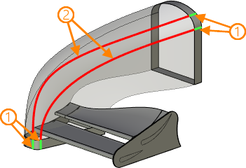
This method is used to connect two elements with wire geometry in a transitional 3D way with the ability to control the interface parameters and the boundaries of the extreme points. Elements with wire geometry include all linear objects - edges, 3D paths, cycles, and some types of 3D profiles. Such elements can be either closed or open.

1 – source elements of wire geometry; 2 - resulting 3D paths
The first step in creating a transition 3D path is determining the resulting curve shape: Spline ![]() or Rounding
or Rounding ![]() . It is set with the help of corresponding icons in the parameters window. By default the system sets the curve shape as spline.
. It is set with the help of corresponding icons in the parameters window. By default the system sets the curve shape as spline.
You can select the initial wire objects between which the bridge is to be built at the 3D scene or from the 3D model tree when the following options are enabled:
|
<Q> |
Select Start |
|
<E> |
Select End |
The initial objects end points joined with the 3D path are selected in the same way as the objects, using the corresponding automenu options:
|
<W> |
Select Start Geometry |
|
<R> |
Select End Geometry |
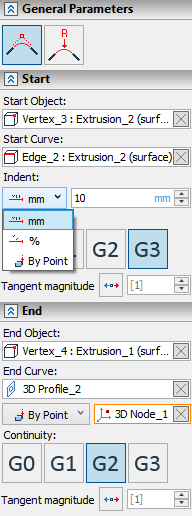
All the selected objects are shown in the corresponding fields in the command properties window. To cancel selection of an object ![]() Clear button is used.
Clear button is used.
Moving the transition 3D path limits along the initial objects can be set in three ways:
•As a value in mm or other units of measurement;
•As a percentage of the initial object length;
•By Point, belonging to the initial object.
For a spline type of curve the kind of joining at the transition interface between the initial object and the resulting 3D path is determined by continuity condition:
•By Point G0 continuity is points coincidence in space;
•By Tangent G1 continuity is geometrical continuity in the first derivative;
•By Curvature G2 continuity is geometrical continuity in the second derivative;
•By Flow G3 continuity is geometrical continuity in the third derivative.
For G1, G2 and G3 continuity conditions it is allowed to set Tangent magnitude value – it is a coefficient scaling derivative value in the given direction. By default this value is equal to [1].

Initially the transition curve is built so that it forms a direct touch with the initial object. You can change the touching direction to the opposite one by clicking ![]() .
.
When creating a transitional 3D path of a spline shape, it is allowed to assign supporting surfaces (surfaces on which the resulting curve should lie). The selection is made using the following automenu option:
|
<T> |
Select Supporting Geometry |
All selected surfaces are displayed in the corresponding list of the command parameters window.
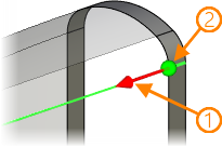
You can control Indent and Tangent magnitude parameters in 3D window using manipulators. You can disable displaying them in the Options tab of the parameters window.

Initial objects conjugation with a rounding type of curve is determined by Radius parameter. By default its value is set in millimeters, but it is allowed to change units of measurement.

Sew option is used to join the resulting transition curve and initial objects into one 3D path.
