Isoparametric Curve |
  
|
Calling the command:
Icon |
Ribbon |
|
Support Geometry > 3D Path > Isoparametric Curve |
Keyboard |
Textual Menu |
<3KCU> |
|
Automenu of the |
|
<I> |
Isoparametric Curve |
This method is designed to generate isoparametric curves (isocurves) on a selected surface (including imported ones). Isoparametric curves should be understood as curves representing the skeleton of any surface. Thus, the generated isoparametric curves can be used as a reference to the selected surface.

This method involves several options for the position of the isocurves:
•Uniform. In this case, the specified number of isoparametric curves is located uniformly over the entire surface in the specified directions.
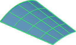
•Through Points. In this case, the position of the isocurves is determined by parametric points. The points are determined by the values of the parameters U and V. In addition, any geometric points of the model can be used as parametric points – 3D nodes, vertices, edge centers.
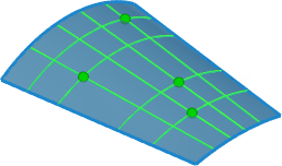
If the geometric points of the model are used as parametric points that determine the position of isocurves, the latter do not necessarily belong to the selected surface.
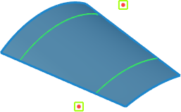
•Between Points. In this case, the specified number of isoparametric curves is located evenly between two parametric points.
After activating this command, you need to select the surface on which you want to get curves. The selection is made in the 3D scene (using ![]() ) or in the 3D model tree when the option is enabled:
) or in the 3D model tree when the option is enabled:
|
<S> |
Select Surface |
The selected object is displayed in the Face field in the parameters window. The selected object is canceled using the Clear ![]() button.
button.
The next step in generating isocurves is to determine their direction: in the direction of U, V or UV. To do this, the corresponding buttons are provided in the parameters window.
|
U |
|
V |
|
UV |
The choice of the location of the isocurves is also carried out in the parameters window using the corresponding buttons. Depending on the selected option, the necessary parameters and automenu options are activated.
|
Uniform |
|
Through Points |
|
Between Points |
If the position of the isocurves is uniform, it is necessary to specify their number.
With the Through Points variant of the position of the isocurves, the parametric point is set when the automenu option is enabled:
|
<B> |
Select Point |
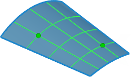
The parametric point is set by clicking the cursor anywhere on the selected surface, followed by changing the parameters U and V. The convenience of managing the parameters U, V is achieved by using manipulators in a 3D scene, the display of which can be disabled on the Options tab if necessary. The values of the point movements along the U, V axes are displayed in the corresponding fields of the parameters window.

The geometric point of the model is selected as a parametric point in the 3D scene (using ![]() ) or in the 3D model tree.
) or in the 3D model tree.

If the geometric points of the model are used as parametric points that determine the position of isocurves, the latter do not necessarily belong to the selected surface.

|
<N> |
Add Point |
With this variant of the arrangement of isocrives, it is allowed to add an unlimited number of parametric points.
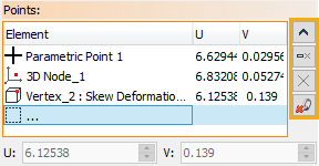
All the specified points are displayed with the values of the parameters U, V in the corresponding list in the parameters window. The list of points is controlled using the Expand ![]() , Collapse
, Collapse ![]() , Delete Element from the list
, Delete Element from the list ![]() , Clear
, Clear ![]() buttons. The Delete Geometric Binding
buttons. The Delete Geometric Binding ![]() button is designed to remove the binding of a parametric point to a geometric one.
button is designed to remove the binding of a parametric point to a geometric one.
In the Between points variant of the isocurves position, it is necessary to specify two parametric points between which curves will be generated, as well as the required number of curves.
By default, the resulting set of generated isoparametric curves is created as separate 3D paths. If necessary, it is allowed not to divide the set of isocrives into separate 3D paths. To do this, uncheck the Split flag in the Options tab in the command parameters window.
