Conic Curve |
  
|
Calling the command:
Icon |
Ribbon |
|
Support Geometry > 3D Path > Conic Curve |
Keyboard |
Textual Menu |
<3KCC> |
|
Automenu of the |
|
<W> |
Conic Curve |
Conic curves are curves of conic sections, i.e. obtained as a result of the intersection of a straight circular cone with planes that do not pass through its vertex.
Depending on the position of the secant plane, the following types of conical curves are distinguished:
•If the secant plane cuts off all the forming cones at the points of one of its cavities, then as a result, the intersection line is a closed curve - an ellipse. A circle is a special case of an ellipse when the secant plane is perpendicular to the axis of the cone.
•If the secant plane is parallel to one of the tangent planes of the cone, then as a result, the intersection line is an open, infinite curve - a parabola lying entirely on one cavity of the cone.
•If the secant plane intersects both cavities of the cone, then as a result, the intersection line is a hyperbola – two identical open parts extending to infinity (branches of the hyperbola), each of which lies on its own cavity of the cone.
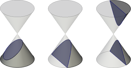
Five geometric conditions are sufficient to form any type of conical curve. These conditions can be:
•Extreme points of a conical curve;
•Inner points of a conical curve;
•Guides of a conical curve at its extreme points;
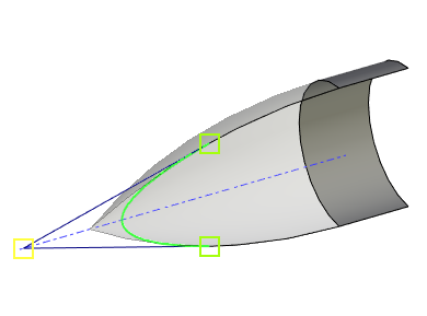
•The vertex is the intersection point of the guides of the conical curve;
•Engineering discriminant is a coefficient that characterizes the degree of convexity of a conical curve. Is equal to the ratio of the part of the median bounded by the curve (h) to the length of the entire median (H) of the triangle formed by the vertex and the extreme points of the curve.
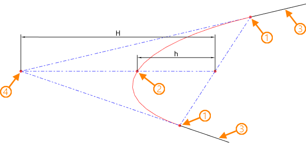
1 – extreme points; 2 - inner point; 3 - guides; 4 - vertex
Thus, the value of the engineering discriminant varies from 0 to 1. With a value greater than 0.5, the resulting curve has the shape of a hyperbola; with a value equal to 0.5, it has the shape of a parabola; with a value less than 0.5, it has the shape of an ellipse.

Discriminant = 0.25 Discriminant = 0.5 Discriminant = 0.75
Depending on the combination of geometric conditions, the system provides six modes for constructing a conical curve:
|
By 5 Points |
|
By 2 Points, 2 Guides and Discriminant |
|
By 3 Points and 2 Guides |
|
By 2 Points, Vertex and Discriminant |
|
By 3 Points and Vertex |
|
By 4 Points and Guide |
For each characteristic point of a conical curve, it is allowed to specify an additional curve along which the point can be offset. The offset is set relative to the nearest end of the specified curve in the parameters window. The convenience of displacement control is achieved by using a manipulator in the form of a point in a 3D scene.
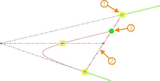
1 - characteristic point of the conical curve; 2 - offset curve; 3 - offset manipulator
The resulting conical curve lies in a plane determined by the system automatically. If necessary, it is allowed to explicitly specify the plane to which the curve should belong. In this case, all objects that do not belong to the specified plane are projected onto it, and the curve is formed based on their projections.

1 – source objects that do not lie in the target plane; 2 - target plane; 3 - projections of the source objects on the target plane; 4 - resulting curve.
The conic curve construction mode is selected in the parameters window. Depending on the selected mode, the set of source data and the composition of the window changes.
To select the geometric points of the model as characteristic points (initial, internal, final) of the conical curve, use the following option:
|
<O> |
Select Conic Curve Points |
Objects are selected in the 3D scene (using ![]() ) or in the 3D model tree.
) or in the 3D model tree.
All selected points are displayed as a list in the parameters window in the appropriate sequence. The list of points is controlled using the Expand ![]() , Collapse
, Collapse ![]() , Delete Element from the list
, Delete Element from the list ![]() , Clear
, Clear ![]() buttons.
buttons.
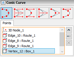
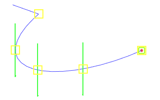
To replace an object used as one of the characteristic points of a conical curve, select it from the list, and then specify a new geometric object.
Specifying a curve to offset the current characteristic point along it is carried out in a 3D scene or a model tree using the following automenu option:
|
<C> |
Select Curve |
The selected object is displayed in the Curve field in the parameters window. Cancel and re-select by clicking the Clear ![]() button. The offset value is set in model units in an adjacent field or using a manipulator in a 3D scene.
button. The offset value is set in model units in an adjacent field or using a manipulator in a 3D scene.
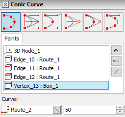
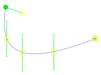
If the selected point of the conical curve belongs to a specific wire object (edge, 3D path, etc.), then the latter is automatically selected as an offset curve.
The conic curve guide is set after selecting the extreme point in the list of points and using the following automenu option:
|
<T> |
Select Guides of Conic Curve |
The object is selected in the 3D scene (using ![]() ) or in the 3D model tree.
) or in the 3D model tree.
The selected object is displayed in the Guides field in the parameters window. Cancel and re-select by clicking the Clear ![]() button.
button.
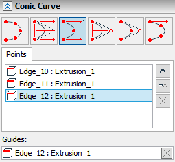
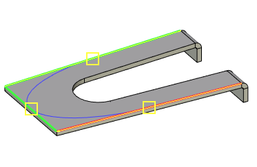
To set a geometric point as the vertex of a conical curve, a special automenu option is provided:
|
<V> |
Select Vertex of Conic Curve |
The object is selected in the 3D scene (using ![]() ) or in the 3D model tree.
) or in the 3D model tree.
The selected object is displayed in the Vertex field of the parameters window. Cancel and re-select by clicking the Clear ![]() button.
button.
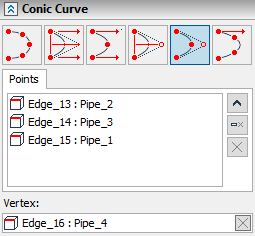
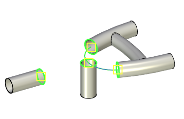
To control the engineering discriminant, a special slider is provided in the parameters window that allows you to change the value from [0] to [1] in increments of [0.01]. If necessary, you can enter the value manually.
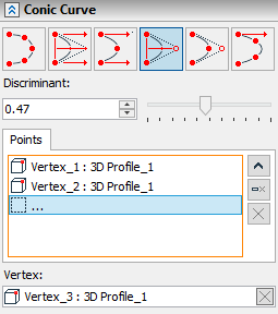
Specifying the target plane to which the conic curve should belong is done using the following automenu option:
|
<L> |
Select Conic Curve Plane |
The selected plane is displayed in the corresponding field of the parameters window. Cancel and re-select by clicking the Clear ![]() button.
button.
The offset manipulators of the characteristic points of the conical curve along the curves in the 3D scene are displayed using the Use Manipulators option.

The Sew option is designed to combine a conical curve with the offset curves of the extreme points into one 3D path.