Split 3D Path |
  
|
Calling the command:
Icon |
Ribbon |
|
Support Geometry > 3D Path > Split Path |
Keyboard |
Textual Menu |
<3KPD> |
|
Automenu of the |
|
<K> |
Split Path |
This way enables users to create 3D paths by means of splitting the existing one into parts using other model objects. The initial 3D path can be either closed or open-loop. 3D points belonging to the initial 3D path or linear objects, sheet bodies and solid bodies crossing the initial 3D path can be used as splitting objects. Several splitting objects for the path to be split are also possible.
As a result of the operation copies of the initial 3D path are generated which correspond to the segments between the objects used for splitting.
|
|
You can choose the 3D path to be split at the 3D scene or from the model tree when the following option is enabled:
|
<G> |
Select 3D Path |
Splitting objects are selected in the same way as the 3D path to be split when the following option is enabled:
|
<S> |
Select splitting object |
You can cancel selection of all the elements with the help of the following option:
|
<F> |
Cancel selection |
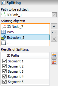
The objects selected are shown in corresponding fields in the command parameters window. To control the list of the objects selected as the second element, Expand ![]() , Collapse
, Collapse ![]() , Delete Element from the List
, Delete Element from the List ![]() , Clear
, Clear ![]() buttons are used.
buttons are used.
The segments obtained after splitting the selected 3D path are shown in Results of Splitting field. The flag set indicates creating a 3D path at this section after confirming the command. You can set on and off all the flags at the same time using Select All ![]() , Clear
, Clear ![]() buttons.
buttons.
