3D Path by 2D Elements |
  
|
Calling the command:
Icon |
Ribbon |
|
Support Geometry > 3D Path > 3D Path by 2D Elements |
Keyboard |
Textual Menu |
<3KPE> |
|
Automenu of the |
|
<H> |
By 2D Elements |
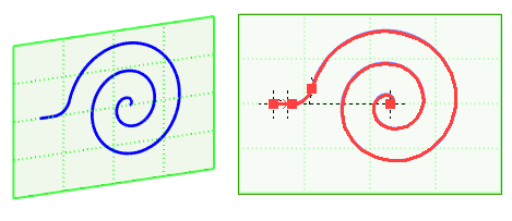
2D elements on the basis of which 3D paths can be created include hatching, construction elements (2D paths, circles, ellipses, splines, offset curves and functions), as well as graphic and sketch lines located on pages associated with workplanes or worksurfaces. When using 2D elements lying on the workplane page, the resulting 3D path will be flat. A 3D path created based on 2D elements lying on the worksurface will repeat the shape of the surface used.

You can select 2D elements basing on which a 3D path is to be built with the following automenu option:
|
<H> |
Select Source Elements |
Creating a 3D path using open construction elements, graphic and sketch lines involves their sequential connection: based on each next selected object, another section of the created path is built; all the obtained sections are combined into one 3D path.
When using hatches, closed construction elements, graphic lines or a sketch as the source, the resulting path is built along the contour of the selected object. In this case, let 3D always be closed.


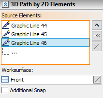
The objects selected are shown in corresponding fields in the command parameters window. To control the list of the objects selected as the second element, Expend ![]() , Collapse
, Collapse ![]() , Delete Element from the List
, Delete Element from the List ![]() , Clear
, Clear ![]() buttons are used.
buttons are used.
To cancel selection of an object as a work surface Clear ![]() button is used.
button is used.
By default, the system aims to automatically determine the worksurface to which the selected 2D elements belong. The found worksurface is displayed in the corresponding field in the parameters window. If the automatic selection turned out to be incorrect or it is necessary to select another worksurface to which the resulting path should belong, use the following automenu option:
|
<W> |
Select Work Surface |
Additional snap
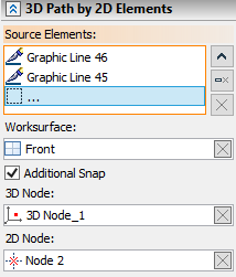
By default, a 3D path created based on 2D elements belonging to the current worksurface will coincide with it in space. However, the system provides for the possibility of changing the position of the 3D path. This is achieved by using an additional binding to the 3D node through which the surface of the profile being created will pass. In addition, it is allowed to clarify the position of the 3D path in space by specifying a 2D node (on the current worksurface) that should be aligned with the selected 3D node.

Changing the position of the 3D path is carried out after activating the Additional Snap parameter, followed by selecting a 3D node in the 3D scene or model tree and, if necessary, specifying a 2D node on the active worksurface. Cancellation and re-selection of nodes is carried out using the Clear ![]() button .
button .
