Spline based on 3D Nodes |
  
|
Calling the command:
Icon |
Ribbon |
|
Support Geometry > 3D Path > Spline based on 3D Nodes |
Keyboard |
Textual Menu |
<3KPS> |
|
Automenu of the |
|
<S> |
Spline based on 3D Nodes |
The 3D path in the form of a spline is built on the basis of the original (control) 3D points. Any geometric points of the model can be used as initial (control) points - 3D nodes, vertices, characteristic points of edges, faces, bodies.
There are three types of 3D splines:
•3D polyline;
•3D spline through nodes;
•3D spline by polyline.
Any type of 3D spline can be open or closed (periodic). In the case of a periodic spline, the last selected geometric point is automatically connected to the first one.
At least three control points are required to construct a closed spline of any type.

1 – closed 3D polyline; 2 – closed 3D spline by points; 3 – closed 3D spline along a polyline
3D polyline
3D polyline is a spatial curve made of straight segments connecting the points of the source set. A polyline can be either open or closed (when a closed polyline is created, the first 3D point of the source set is used twice – for defining the start and the end of the path);
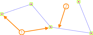
1 – source geometrical points; 2 – 3D polyline
By default, a polyline is a special case of a 3D spline of the first degree.
3D spline through nodes
3D spline through nodes is a spline passing through all control points (nodes). In this case, the control points (nodes) are the selected geometric points of the model.
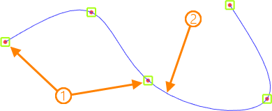
1 – source geometrical points; 2 – 3D spline through nodes
The main parameter of this type of spline is its Degree – the degree of the polynomials of the piecewise continuous function by which it is described. The maximum allowable value of the degree is one less than the control points (nodes) of the spline. For splines with more than four control points (nodes), third degree polynomials are used by default.
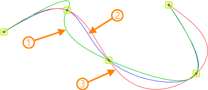
Shape of 3D spline through nodes, depending on its degree: 1 - spline of the second degree; 2 - spline of the third degree; 3 - spline of the fourth degree
Also, the features of this type of spline include the ability to set its direction at each control point (node). The direction is determined by a special object - a tangent. Thus, the resulting spline will touch the specified direction at the current point (node).
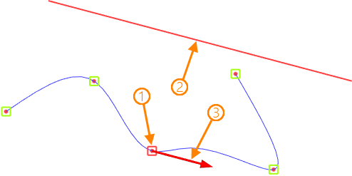
1 – current point; 2 - tangent that defines the direction of the spline at the current point; 3 - vector of the direction of the spline at the current point
The control point (node) of the spline does not have to belong to the guiding object.
At the control points (nodes) of the spline, it is allowed to determine the nature of the conjugation by the nodes in contact with other curves. The following options are provided:
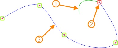
1 – source curve for the mating; 2 - mating point; 3 - 3D spline through the nodes
•Continuity G0 - assumes a coincidence in the space of mating curves at the current point (node).
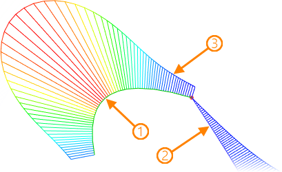
Mating of 3D spline with an source curve with continuity G0: 1 – initial curve for mating; 2 - resulting 3D spline through nodes; 3 - curvature plot
•Continuity G1 - assumes that the tangent directions of the mating curves coincide at the current point (node).
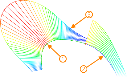
Mating of 3D spline with the source curve with continuity G1: 1 – source curve for mating; 2 - resulting 3D spline through nodes; 3 - curvature plot
•Continuity G2 - assumes the coincidence of the tangent directions of the mating curves and the equality of their curvature at the current point (node).
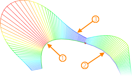
Mating of 3D spline with an source curve with continuity G2: 1 – source curve for mating; 2 - resulting 3D spline through nodes; 3 - curvature plot
•Continuity G3 - assumes the coincidence of the tangent directions of the mating curves, the equality of their curvature, as well as the preservation of the smoothness of the curvature at the current point.
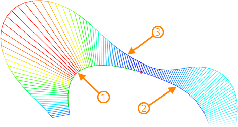
Mating of 3D spline with an source curve with continuity G3: 1 – source curve for mating; 2 - resulting 3D spline through nodes; 3 - curvature plot
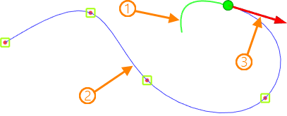
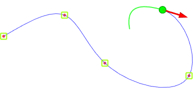
With continuity G1 G2 G3, it is allowed to set the value of the Tangent magnitude - a coefficient that scales the value of the length of the tangent vector. By default, the value is [1]. The convenience of controlling the tangent module is achieved by using a special manipulator - an arrow - in a 3D scene.
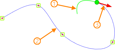
Tangent magnitude = 1
Tangent magnitude = 2
1 – source curve for mating; 2 - resulting 3D spline through the nodes; 3 - manipulator for controlling tangent magnitude
The direction of contact of the spline at the point of interface with another curve can be changed to the opposite.
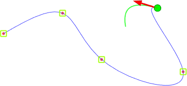
3D spline by polyline
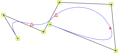
3D spline by polyline (a NURBS – non-uniform rational B-spline) – an arbitrary-degree spline by a control polyline. The selected geometric points of the model are used to construct a control polyline. The spline itself does not pass through them (except for the first and last points in the case of an open (open) spline).
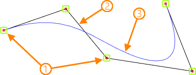
1 – source geometric points; 2 - control polyline; 3 - 3D polyline spline
In addition to the Degree, one of the main characteristics of this type of spline is the Weight - the weight coefficient of the control point. The greater the weight of the point, the closer the curve passes to it. By default, the weight for all control points is [1].
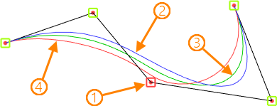
1 - control vertex; 2 - 3D spline with weight [1] at the control point; 3 - 3D spline with weight [2] at the control point; 4 - 3D spline with weight [3] at the control point
Another parameter of this type of spline that affects its geometry is the type of parametrization that determines the intervals between the mathematical nodes of the spline. The following types are provided:
•By Chord – the placement of mathematical nodes is proportional to the distances between each connected pair of control points.
•Uniform – mathematical nodes are placed at an equal distance from each other regardless of the distance between the control points. Since the shape of the curve does not adapt to the lengths of the segments of the control polyline, folds and loops can be obtained on small segments.
•Centripetal – the placement of mathematical nodes is proportional to the square root of the distance between each connected pair of control points.
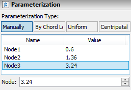
•Manually. This type of parametrization assumes an independent determination of the position of mathematical nodes. For convenience, special manipulators are designed in the 3D scene.
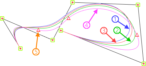
Shape of the spline depends on the type of parametrization: 1 - by chrord; 2 - uniform; 3 - centripetal; 4 - manually; 5 - manipulators for controlling the parametrization nodes.
Any control point of the 3D path can be shifted relative to the source position. To do this, it must belong to a spatial curve. Thus, the offset of the control point is carried out along this curve.
If the source geometric point does not belong to the curve, then the projection of the geometric point on this curve will be used as the control point of the spline.
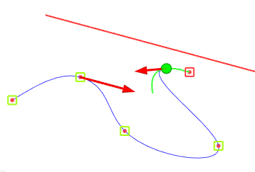
Any wire object of the model can be selected as a curve. The offset of the control point relative to the beginning of the selected curve can be controlled by the parameters window, as well as directly in the 3D scene by using a special manipulator in the form of a sphere.
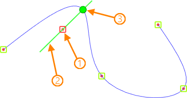
1 – source control point; 2 - curve for the offset of the source control point; 3 - offset manipulator
For a 3D path as a spline through nodes, the selected curve by default is also its tangent (a reference to the tangent) at the current control point.
Creating 3D path as 3D spline by 3D points
Creating a 3D spline usually begins with specifying a set of 3D points on which the spline will be constructed. To select 3D points, use the option:
|
<M> |
Add 3D Point to Spline |
All selected 3D points are sequentially entered into the corresponding list of control points of the spline in the parameters window. For each control point, depending on the type of spline, the specified additional parameters are displayed. The list is managed using the Expand ![]() , Collapse
, Collapse ![]() , Delete Element from the List
, Delete Element from the List ![]() , Clear
, Clear ![]() buttons.
buttons.
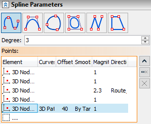
The type of the resulting 3D spline is selected using the corresponding icons in the parameters window:
|
Through Nodes |
|
By Polyline |
|
Closed Spline Through Nodes |
|
Closed Spline By Polyline |
|
Polyline |
|
Closed Polyline |
The degree of the 3D spline is set in the corresponding field in the parameters window.
The object defining the direction of the 3D spline through the nodes at the current control point is set using the following automenu option:
|
<T> |
Select Tangent |
The selection is made in the 3D scene (using ![]() ) or in the model tree. At the same time, it is important to pay attention to the state of the element selection filters.
) or in the model tree. At the same time, it is important to pay attention to the state of the element selection filters.
The selected object is displayed in the Tangent field of the parameters window. Cancel and re-select using the Clear ![]() button.
button.
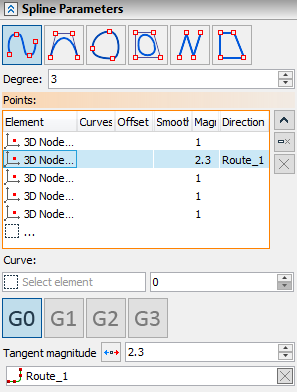
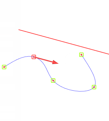
The curve along which the current control point should be shifted is selected using the following automenu option:
|
<C> |
Select Curve |
The object specified as the displacement curve is displayed in the Curve field of the parameters window. The value of the reference point offset is set in model units in the adjacent field.
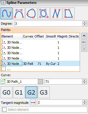
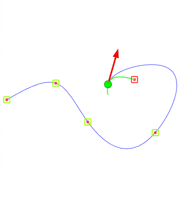
The icons ![]()
![]()
![]()
![]() are designed to determine the type of mating of the 3D spline with the source curve at the current control point. The tangent magnitue is controlled using a manipulator in the form of an arrow in a 3D scene or by changing the value in the parameters window. The touch direction is changed using the icon
are designed to determine the type of mating of the 3D spline with the source curve at the current control point. The tangent magnitue is controlled using a manipulator in the form of an arrow in a 3D scene or by changing the value in the parameters window. The touch direction is changed using the icon ![]() .
.
The value of the weight coefficient of the current control vertex of the spline along the polyline is set after its selection in the special Weight field.
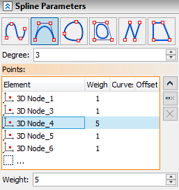
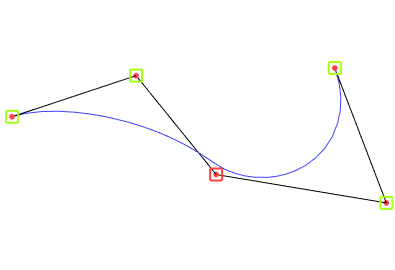
The choice of the type of parametrization of the spline along the polyline is carried out on a special tab of the parameters window. This tab also displays the number and intervals of mathematical nodes of the spline. In Manual mode, the intervals between nodes can be changed – using special manipulators in triangles in a 3D scene or in a special field in the parameters window.
