Compound 3D Path |
  
|
The command can be called in one of the following ways:
Icon |
Ribbon |
|
Support Geometry > 3D Path > Compound 3D Path |
Keyboard |
Textual Menu |
<3KPO> |
|
Automenu of the |
|
<T> |
Compound 3D Path |
This method allows you to create a 3D path by combining various elements of wire geometry. Such elements include the edges of 3D paths, sheet and solid bodies, and directly 3D paths. The source elements should not be closed. The direction of the resulting path is determined by the direction of the first selected element.
In general, a 3D path is formed by a simply connected sequence of elements, while the direction of the resulting path is determined by the direction of the first element of this sequence; the direction of the remaining elements is determined automatically.
If unrelated elements are used in the formation of a 3D path (i.e. elements that do not have common vertices), the system provides three modes of linking them:
•Auto Joining Mode ![]() . In this mode, the beginning of an unrelated element is connected to the end of the previous section by a straight segment.
. In this mode, the beginning of an unrelated element is connected to the end of the previous section by a straight segment.
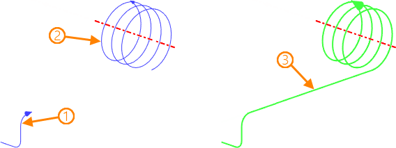
1, 2 - source elements in the order of selection; 3 - resulting 3D path
•Move ![]() . In this mode, the beginning of an unrelated element is connected to the beginning of the previous sequence by the parallel transfer method.
. In this mode, the beginning of an unrelated element is connected to the beginning of the previous sequence by the parallel transfer method.
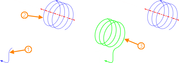
1, 2 - source elements in the order of selection; 3 - resulting 3D path
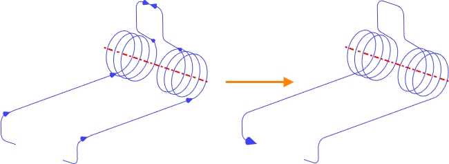
•Auto ![]() . In this mode, the system analyzes a set of selected elements for the formation of a simply connected sequence, regardless of their order. Otherwise, the elements in the order of their selection, taking into account the original direction, are connected by the parallel transfer method.
. In this mode, the system analyzes a set of selected elements for the formation of a simply connected sequence, regardless of their order. Otherwise, the elements in the order of their selection, taking into account the original direction, are connected by the parallel transfer method.
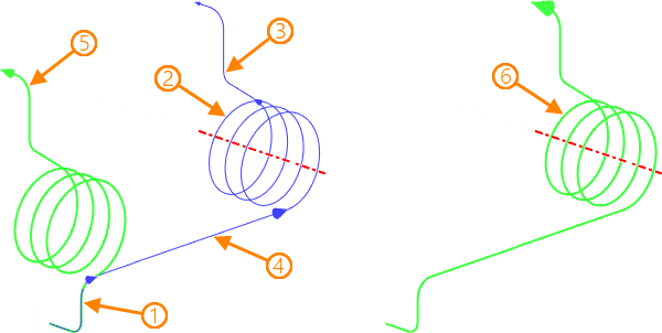
1, 2, 3, 4 – source elements in the order of selection; 5 - resulting 3D path when selecting the first three elements; 6 - resulting 3D path when selecting all elements
In the Auto Joining and Move modes, the direction of unrelated elements is determined by the cursor position when they are selected in a 3D scene: the edge of the element to which the cursor is closer at the time of selection is the end. If necessary, the direction of unrelated elements can be reversed.

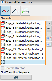
All selected items are entered in the list. The order in which the sections of the 3D path are connected corresponds to their position in the list. By moving the required item through the list, the connection order changes.
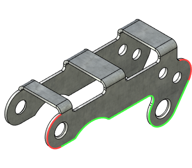
In the Auto Joining mode, the Find Transition Sequence function is available, designed to automatically search for a sequence with a minimum set of edges between selected edges of the same body.

1 – source edges of the body; 2 - resulting 3D path along the found sequence
Creating compound 3D path
The joining mode is selected using the corresponding icons in the command parameters window.
The elements are selected in the 3D scene (using ![]() ) or in the 3D model tree when the option is enabled:
) or in the 3D model tree when the option is enabled:
|
<T> |
Select Element |
The sequence of smoothly coupled elements is selected when the corresponding option is enabled in the selector settings.
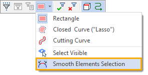
After enabling this option, it is enough to specify any element included in the required sequence. The remaining elements will be selected automatically.
All selected items are displayed in the corresponding list in the command parameters window. To manage the list, use the Expand ![]() , Collapse
, Collapse ![]() , Delete Element from the List
, Delete Element from the List ![]() , Clear
, Clear ![]() buttons. The selected item is moved through the list using the buttons Move Up
buttons. The selected item is moved through the list using the buttons Move Up ![]() , Move down
, Move down ![]() .
.
The Reverse direction flag is used to reverse the direction of the current unrelated element.
The Find Transition Sequence function is activated in the Auto Joining Mode.
