3D Path by Two Projections |
  
|
Calling the command:
Icon |
Ribbon |
|
Support Geometry > 3D Path > 3D Path by 2 Projections |
Keyboard |
Textual Menu |
<3KPJ> |
|
Automenu of the |
|
<Q> |
By Two Projections |
This method allows you to create a 3D path based on two projections located in non-parallel planes. Image lines, 2D paths and 3D paths, as well as 3D profiles and edges can be used as projections. A 3D path is constructed at the intersection of two imaginary surfaces formed by moving projections in specified directions.

This example is located in the Examples library, the 3D Modeling/Paths/3D Path by two 2D Paths.GRB.
Upon calling the command following options appear in the automenu:
|
<F> |
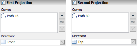
Select first projection (2D Path) |
|
<S> |
Select second projection (2D Path) |
These options allow you to select objects as projections of the created path.
Each projection can include several objects.
By default, the system seeks to automatically find objects that determine the direction of projection in such a way that the resulting path is orthogonal to the planes in which the projections lie. If necessary, it is allowed to explicitly specify objects (plane, face, profile) that determine the direction of projection. In this case, the selection is made in the 3D scene (using ![]() ) or in the 3D model tree when the option is enabled:
) or in the 3D model tree when the option is enabled:
|
<W> |
Select Other Workplane |
All selected items are displayed in the corresponding list in the command parameters window. To manage the list, use the Expand ![]() , Collapse
, Collapse ![]() , Delete Element from the List
, Delete Element from the List ![]() , Clear
, Clear ![]() buttons.
buttons.
