Combining Modes of Projecting Elements onto Workplane |
  
|
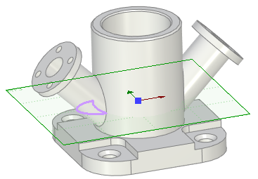
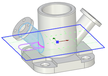
Modes of the Project Elements command can be combined to obtain the necessary constructions on the workplane. For example, instead of the full outline of the inclined flange's cylindrical face, let's create the projection of outline of those part of this face, which is below the workplane. To do this, first we need to activate a workplane that intersects the inclined cylindrical face of the flange.
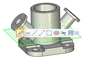
Next, call the Project Elements command from the Ribbon and switch it to the Intersections with Workplane mode using buttons in the parameters window, then select the face of the flange.
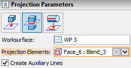
Finish the input via ![]() or <Ctrl + Enter>.
or <Ctrl + Enter>.
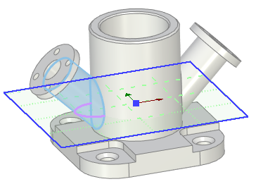
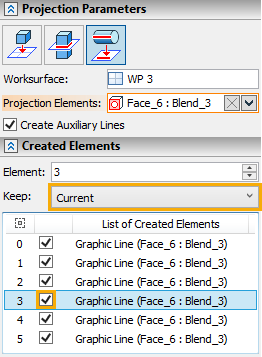
Next, call the Project Elements command again, but this time use the Projection of Elements Outline to Workplane mode, and then select the same face again. In the Created Elements tab of the parameters window set the Keep parameters to Current and select the necessary line in the list of lines.
Finish the input via ![]() or <Ctrl + Enter>.
or <Ctrl + Enter>.
The resulting contour is the projection of outline of those part of the face, which is below the workplane.
