Projection of Elements Outline to Workplane |
  
|
Using this mode of the Project Elements command, you can project an outline of a body's faces on the active workplane along the normal direction. Only ![]() faces are available in the selction filter of this mode.
faces are available in the selction filter of this mode.
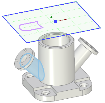
For example, let's project the outline of the inclined cylindrical face of the flange onto the horizontal workplane. To do this, first we need to make the workplane active, next call the Project Elements command from the Ribbon and switch it into the Projection of Elements Outline to Workplane mode using buttons in the parameters window. Then we have to select the desired face in the 3D window.
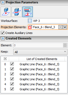
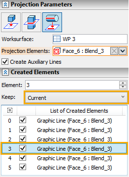
The name of the active workplane is displayed in the Worksurface box in the Projection Parameters tab of the parameters window; names of selected faces and their parent operations - in the Projection Elements box. You can ![]() Expand,
Expand, ![]() Collapse,
Collapse, ![]() Clear the list of selected faces or
Clear the list of selected faces or ![]() Delete Element from the List using buttons located at the right side of the Projection Elements box.
Delete Element from the List using buttons located at the right side of the Projection Elements box.
The Create Auxiliary Lines checkbox is located in the bottom of the tab. It is enabled by default, so all resulting lines are will be auxiliary and won't be used for 3D profiles creation.
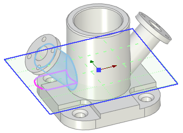
If we want to create the full outline contour of the selected face, then all that's left to do is finishing the input using ![]() or <Ctrl>+<Enter>.
or <Ctrl>+<Enter>.
The active workplane can either intersect or not intersect the face. In any case, a full outline contour will be constructed.
If you don't need to create a full outline contour, use the use the Created Elements tab in the parameters window. The bottom of the tab contains the list of all lines, that form the full outline contours of the selected faces. Click ![]() a line in the list to select it. Selected line is displayed in brighter color in the 3D window. Each line in the list has a checkbox. Depending on the status of the Keep parameter and intersections' checkboxes, finishing the input (via
a line in the list to select it. Selected line is displayed in brighter color in the 3D window. Each line in the list has a checkbox. Depending on the status of the Keep parameter and intersections' checkboxes, finishing the input (via ![]() or <Ctrl>+<Enter>) may result in creation of some particular lines instead of creating the full outline contour. The drop-down list of the Keep parameter contains following options:
or <Ctrl>+<Enter>) may result in creation of some particular lines instead of creating the full outline contour. The drop-down list of the Keep parameter contains following options:
•Current
Finishing the input results in creating only a single line, the one that is selected in the list, regardless of the state of lines' checkboxes. Selecting this option activates the Element input box in the top of the Created Elements tab. This input box contains the index number of line, which is currently selected in the list. Changing the value switches the selection in the list to the corresponding line.
•All
Finishing the input results in creation of all possible lines, regardless of the state of their checkboxes.
•Selected
Finishing the input results in creation of lines, whose checkboxes are enabled.
•All Excluding Selected
Finishing the input results in creation of lines, whose checkboxes are disabled.
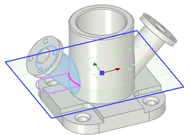
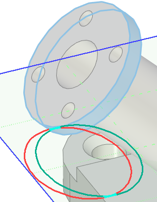
Not only the outer contours of the faces are projected, but also the inner outlines of the faces, except the ones obscured by the face itself. This is well illustrated by an example of a projection of an outline on a cylindrical face of a flange. The red lines correspond to the outline of upper edge, the green lines correspond to the outline of the lower edge. Turquoise lines correspond to the area, where outlines of both edges coincide. Color in the picture are edited manually for demonstration purposes - such differentiation of colors is not provided within the actual command.
