Intersections with Workplane |
  
|
Using this option of the Project Elements command, elements formed by intersection of active workplane with edges, edges, profiles, paths or other workplanes and work surfaces can be created on the active workplane. Elements of the listed types are selected using the corresponding filters.
![]()
When the active workplane intersects edges, profiles, or other workplanes and work surfaces, they are projected as lines. When the active workplane intersects edges or paths, they are projected as points.
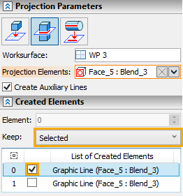
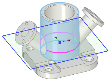
For example, you can get the line of intersection of the flange faces with the workplane passing through the body of the flange. To do this, you need to make the workplane active, then call the Project Elements command from the Ribbon and select the Intersections with Workplane mode in the parameters window. Next you need to select the faces of the flange.
The name of the active workplane is displayed in the Worksurface box in the Projection Parameters tab of the parameters window; names of selected elements and their parent operations - in the Projection Elements box. You can ![]() Expand,
Expand, ![]() Collapse,
Collapse, ![]() Clear the list of selected elements or
Clear the list of selected elements or ![]() Delete Element from the List using buttons located at the right side of the Projection Elements box.
Delete Element from the List using buttons located at the right side of the Projection Elements box.
The Create Auxiliary Lines checkbox is located in the bottom of the tab. It is enabled by default, so all resulting lines are will be auxiliary and won't be used for 3D profiles creation.
If you select the outer faces, the outer contour of the flange section by the workplane is created.
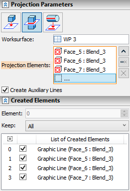
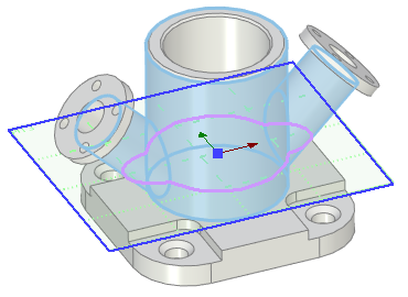
If you select both outer and inner faces, the complete contour of the nozzle section by the workplane is created.
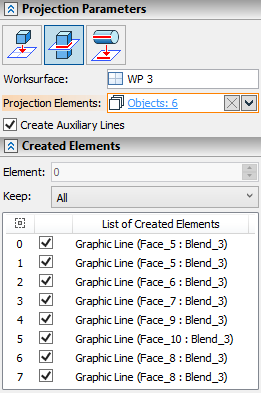
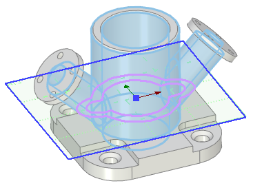
A single element may have multiple lines or points of intersection with workplane. If you don't need to create all of them, use the Created Elements tab in the parameters window. The bottom of the tab contains the list of all intersections (lines and points) between selected elements and active workplane. Click ![]() a line in the list of intersections to select a particular intersection. Selected intersection is displayed in brighter color in the 3D window. Each intersection in the list has a checkbox. Depending on the status of the Keep parameter and intersections' checkboxes, finishing the input (via
a line in the list of intersections to select a particular intersection. Selected intersection is displayed in brighter color in the 3D window. Each intersection in the list has a checkbox. Depending on the status of the Keep parameter and intersections' checkboxes, finishing the input (via ![]() or <Ctrl>+<Enter>) may result in creation of some particular lines and points instead of creating the full set of intersections. The drop-down list of the Keep parameter contains following options:
or <Ctrl>+<Enter>) may result in creation of some particular lines and points instead of creating the full set of intersections. The drop-down list of the Keep parameter contains following options:
•Current
Finishing the input results in creating only a single intersection, the one whose line is selected in the list, regardless of the state of intersections' checkboxes. Selecting this option activates the Element input box in the top of the Created Elements tab. This input box contains the index number of intersection, which is currently selected in the list. Changing the value switches the selection in the list to the corresponding element.
•All
Finishing the input results in creation of all possible intersections, regardless of the state of their checkboxes.
•Selected
Finishing the input results in creation of intersections, whose checkboxes are enabled.
•All Excluding Selected
Finishing the input results in creation of intersections, whose checkboxes are disabled.
If you select the edges of the flange instead of faces, then the result of the command will be 2D nodes.
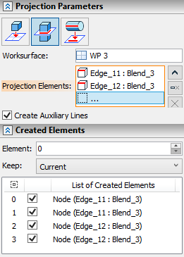
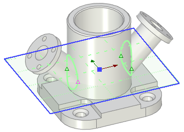
As can be seen from the example, two selected edges create projections of four points, since each edge has two intersections with the active workplane. If you need only one intersection point of several, then you have to use the Created Elements tab as described above.