Projection to Workplane |
  
|
You can project a Face, Edge, Vertex, Profile, Patch, 3D Node on the plane while in the mode of drawing on the active workplane. To do this, call the Project Elements command in the Ribbon and select the Projection to Workplane mode (active by default).
The filters toolbar displays a list of all possible 3D elements for projecting in this way by default.
![]()

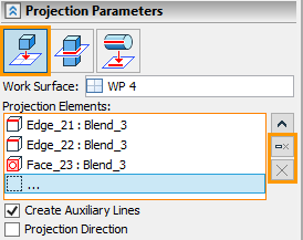
You should select the projection option in the command parameters (in this case, the first one). The active workplane and elements are automatically selected. The list of selected items can be completely cleared using the icon ![]() , or cancel selection of any element using
, or cancel selection of any element using ![]() .
.
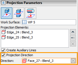
The following two options are also available: Create Auxiliary Lines and Project Direction. In the first option is enabled, all lines created using projecting will be auxiliary.

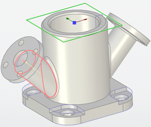
If the second option is disabled, then the projection is performed along the normal to the workplane. If the option is enabled, then it is necessary to specify the direction of projecting the element on the workplane. The direction may specified by an edge, a normal to a face or an axis of a cylindrical surface.
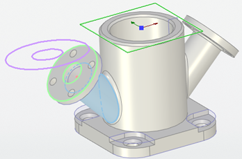
For example, you can project the edges of the flange in the direction of its axis. Then in the Project Direction option field you need to select a cylindrical face: the axis of the cylindrical face will set the direction of projection.


As a result, projection lines will be created on the active workplane. In this case, the auxiliary lines are created as the appropriate option was enabled.
|
|
Normal projection (without using Project Direction option) |
Projection by Direction (using the Project Direction option) |