Create Route |
  
|
Creating and editing points
After invoking the Route command the first segment with the start point is automatically created. This point becomes active. A point is considered active when it is highlighted in the list of points in the parameters window. A manipulator of the active point appears in the 3d window.
By default the following option is active in the automenu:
|
<F> |
Select a point |
This option allows you to bind route points to geometric 3D points of the model (3D nodes, vertices, etc.). In this case, the parent geometric object will be displayed in the list of points next to the point name in parentheses.
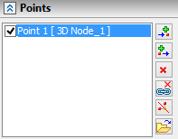
Deleting a point binding to a geometric object is implemented using the following automenu option:
|
<L> |
Delete linking of Point |
After deleting the link, location of the point is stored in absolute coordinates
The system offers two modes of adding points, the choice between which is done by the auto-menu buttons:
|
<H> |
Add Note at the end of Path |
|
<J> |
Add Note at the beginning of Path |
In the case of adding points before the active point, new points are added to the beginning of the segment.
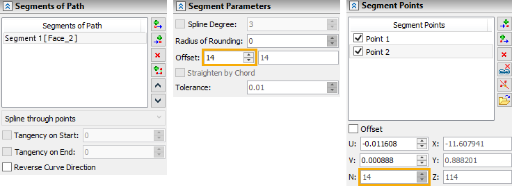
Change the location of the active point by using the manipulator in the 3d window. The absolute coordinates are shown in the parameters window. For points of the segment by surface fields, the U, V, N coordinates are filled in. For points of the segment by edge, the U, V, R coordinates are filled in. Coordinate values can be changed manually.
When creating or editing a point, it is often more convenient to specify the values of offsets, but not their absolute coordinates. For input of this data the group of parameters Offset is used. When creating the new point, its location initially coincides with the point created just now. By specifying the value of the offset, we translate the active point with respect to the previous one. If the offsets are specified upon the editing of the point, then the result will be its translation relative to its current location.
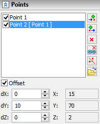
If the Offset flag is set for a point, then it is not recommended to bind this point to a geometric object. The point should be free from geometric binding.
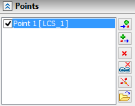
Segment points can be specified in the coordinates of an arbitrary LCS. To select\cancel LCS in automenu use options:
|
<C> |
Select LCS |
|
<V> |
Cancel LCS selection |
After selecting a coordinate system, it will be used for the current point and all points that are created after the current one. LCS deselection transfers the coordinates of the current point to the global coordinate system. Segment of the path can contain any combination of coordinates definition.
A new point creation is performed using the automenu option:
|
<Enter> |
Finish point Editing and create new Point |
The new point is initially located in the same coordinates as the point created just now.
To delete the active point, you need to use the automenu option:
|
<Del> |
Delete Point from Path |
In the parameters window next to the list of points there are the buttons, which also allow us to add the points before ![]() or after
or after ![]() the active point, delete the active point
the active point, delete the active point ![]() , delete link of points
, delete link of points ![]() , split segment into two at the active point
, split segment into two at the active point ![]() , and import points from external file*.txt and *.csv
, and import points from external file*.txt and *.csv ![]() .
.
Depending on the selected curve type, the corresponding point parameters are activated.
Parameters of points are set in the corresponding tab of the parameters window depending on the selected type of the segment of the path.
The Rounding parameter allows you to specify the rounding radius of a Polyline type area at a selected point.
The Tangent parameter sets the same value of the first derivative of the polynomials of the curve before and after the selected point. To set different values, disable the Symmetric flag:
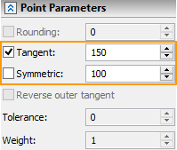
The Reverse outer tangent parameter is used to change the direction of one route when smoothly mating with another.
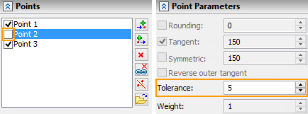
The Tolerance parameter is used for the Spline through points segment type. To set the maximum deviation of a curve from a point, it is necessary to disable the Interpolation Point flag (the other parameters of the point will not be available):
The Weight parameter determines the degree of influence of the selected point on the segment of the Spline by Polyline type.
Creating and Editing Segment
The list of segments of the route is displayed in the corresponding tab of the parameters window. To add a new segment, use the Add... ![]() and Add to End
and Add to End ![]() buttons. To delete the current segment use the Delete
buttons. To delete the current segment use the Delete ![]() button.
button.
When deleting a segment from the middle of the list, the previous and the following segments are connected by a transition zone.
The Merge with Next ![]() button allows you to combine two segments of the same type into one.
button allows you to combine two segments of the same type into one.
The segment can be split at the selected point using the Split ![]() button.
button.
Segments can be moved using the Move Up ![]() and Move Down
and Move Down ![]() buttons.
buttons.
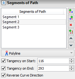
The parameters Tangency on Start and Tangency on End allow you to provide a smooth conjugation between the transition curve and the mating segments. The option Create smooth path provides automatic smoothing of all transition zones between segments. The option is located in the Options tab of the parameters window.
The Reverse Curve Direction parameter allows you to change the direction of the segment to the opposite. This is useful when adding new segments to provide the same direction of the curve in all segments of the route.
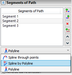
For a segment of the route built on specified points, the type that determines how to build it is selected in the drop-down list on the Segments of Path tab in the parameters window.
The parameters of the curve segment, depending on its type, are set in the corresponding tab of the parameters window.
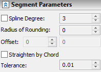
The Spline Degree parameter is used for the Spline through points and Spline by Polyline segment types.
The Radius of Rounding parameter sets the total rounding value for all points of the segment of the Polyline type.
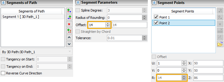
The Offset parameter sets the value of the movement of the segment created by the path/edge and the surface/face, along the normal from the object.
The Straighten by Chord parameter allows setting the value of the maximum deviation of the curve shape from the chord between the interpolation points in the corresponding field for a Spline through points type.
To create a segment based on paths or edges, use the option:
|
<E> |
Create segment by path/edge |
After activating the option, you should specify an object of one of the types:
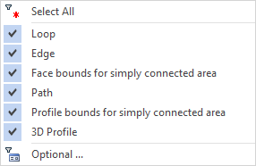
The selected object will set the trajectory of the created segment. The positioning of its starting and ending point is performed with the help of manipulators or by setting the coordinates U, V in the parameters window. The R field duplicates the value of the Offset parameter.
To create a segment based on faces or surfaces, use the option:
|
<S> |
Create segment by surface/face |
After activating the option, you should specify an object of one of the types:
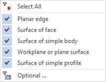
The start point of the segment is created at the place of the mouse click. After that, having added the new point, it can be translated with the help of the manipulator or by specifying coordinates U, V in the parameters window. Coordinate N duplicates values of Offset parameter.
