Create Thread |
  
|
Create Thread |
|
To create an operation, you need to perform the following sequence of actions:
1. Specify the bearing face.
2. Set the thread parameters.
3. Set the boundaries of the beginning and end of the thread (optional).
4. Confirm the creation of the operation.
Specifying the bearing face
The option ![]() (<F>) is active by default after calling the command. Cylindrical and conical faces are available for selection. It is allowed to select several faces of the same type and diameter.
(<F>) is active by default after calling the command. Cylindrical and conical faces are available for selection. It is allowed to select several faces of the same type and diameter.
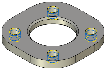
After selecting a face, a schematic image of the thread in the form of a spiral, the thread border is displayed on its surface (by default, the thread is applied to the entire length of the face).
The edge of the face, closer to which the mouse cursor was located at the time of selection, sets the beginning of the thread (i.e. the direction of cutting is postponed from it).
Thread parameters
The operation parameters are displayed in the Parameters service window. You can also open the parameters window using the automenu option ![]() (<P>). The default thread parameters are selected from a special file based on the diameter of the bearing face. With the same diameter of the bearing face, the parameters selected by the system for external and internal threads will be different. For an external thread, the diameter of the bearing face is considered the outer diameter, for an internal thread – the inner one.
(<P>). The default thread parameters are selected from a special file based on the diameter of the bearing face. With the same diameter of the bearing face, the parameters selected by the system for external and internal threads will be different. For an external thread, the diameter of the bearing face is considered the outer diameter, for an internal thread – the inner one.
Defining thread offsets (boundaries)
By default, the thread is created along the entire length of the selected face. To set offsets, you can use the automenu options and the Parameters window or manipulators, which are shown in yellow in the figure. When you hover the cursor over the manipulator, its shape changes to ![]() for the start thread boundary or to
for the start thread boundary or to ![]() - for the end one. By moving the mouse with the left button pressed, you can change the position of the thread boundaries. Numerical values of offsets will be displayed in the Parameters window.
- for the end one. By moving the mouse with the left button pressed, you can change the position of the thread boundaries. Numerical values of offsets will be displayed in the Parameters window.
By default, the offsets are set relative to the start and end of the face. Using the automenu options, you can change the type of indentation assignment.

For the start thread boundary, an option ![]() is used, the drop - down list of which contains icons:
is used, the drop - down list of which contains icons:
|
<A> |
From face start |
The offset of the start of the thread is calculated from the start boundary of the bearing face. The start boundary is considered to be the edge closest to which the cursor was located when selecting the face.
|
<S> |
From Element |
The offset of the start of the thread will be calculated from the additionally selected 3D object. The options for selecting objects of different types are described below.
For the end thread boundary, an option ![]() is used, the drop - down list of which contains icons:
is used, the drop - down list of which contains icons:
|
<D> |
From face end |
The offset is set from the end edge of the bearing face.
|
<F> |
From thread start |
The offset is set from the start thread boundary, i.e. the offset value determines the length of the thread.
|
<G> |
From face start |
|
<H> |
From Element |
This option ![]() allows you to set the offset from the start edge of the bearing face. When using the option
allows you to set the offset from the start edge of the bearing face. When using the option ![]() , the offset of the start of the thread will be calculated from the additionally selected 3D object. The options for selecting objects of different types are described below.
, the offset of the start of the thread will be calculated from the additionally selected 3D object. The options for selecting objects of different types are described below.
If the type of the start or end of the thread is set Object, then additional icons become available in the automenu:
|
<V> |
Select points |
|
<L> |
Select lines |
|
<U> |
Select planes |
Each of these options uses filters to define the set of object types allowed for selection (see Selection of 3D Elements). That is, those objects are available for selection, on the basis of which the system can determine the geometry of a 3D point, straight line or plane.
For example, on a bolt, the thread is created after the chamfer is created, so the start boundary is set from object. An end face or a 3D point belonging to this face can be selected as an object. You can set the type of thread end to Thread start and set the offset to an exact value of the thread length.


The automenu option ![]() (<R>) cancels the selection of the bearing face and the objects that set the offsets.
(<R>) cancels the selection of the bearing face and the objects that set the offsets.
Completing the operation creation
To confirm the creation of the operation, use the option ![]() (<Ctrl>+<Enter>).
(<Ctrl>+<Enter>).
You can edit the operation either by calling the Parameters window again, or by using a special command.