Creating non-Parametric Drawing |
  
|
We will use the same familiar drawing example of the plate with a conical hole. Let’s begin with constructing the main view. Thereafter, we will create two projections, the “Left Side View” and the “Plan View”, using object snapping mechanism.
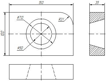
In this case, all constructions are created using the command <SK> Sketch:
Icon |
Ribbon |
|---|---|
|
Draw > Sketch |
Keyboard |
Textual Menu |
<SK> |
Construct > Sketch |
This command can be used to create both a sketch (non-parametric drawing) and a parametric drawing: sketch with constraints. Creating a sketch with constraints will be discussed in the next subsection.
When creating a sketch, object snaps are widely used. Bindings are managed using the "Bindings" panel. The currently activated bindings correspond to pressed panel icons. It is possible to disable the established binding, by clicking on the binding icon using ![]() .
.
![]()
You can disable all bindings by clicking the icon:
|
Clear all sketch Snaps |
All bindings will be enabled after disabling the option. When creating our example, the following bindings will be needed:
|
Line Midpoint |
|
Graphics End Points |
|
Horizontal/Vertical |
|
Orthogonal |
|
Point on Graphic Line |
|
Horizontal/Vertical tangent |
Activate these bindings by clicking ![]() on the corresponding icons in the "Bindings" panel. If the binding has already been enabled, then clicking on its icon will disable it. If the icon is on a blue background - it is enabled, if on gray it is disabled. Object bindings can also be configured in the <SO> Options command, the Bindings tab.
on the corresponding icons in the "Bindings" panel. If the binding has already been enabled, then clicking on its icon will disable it. If the icon is on a blue background - it is enabled, if on gray it is disabled. Object bindings can also be configured in the <SO> Options command, the Bindings tab.
When constructing segments, arcs and circles of the sketch, the coordinates of points can be set by simply clicking ![]() in the drawing field. To accurately specify the coordinates of the nodes, you can use the parameters window.
in the drawing field. To accurately specify the coordinates of the nodes, you can use the parameters window.
After calling the command <SK> Sketch, the following two options are automatically set in the automenu:
|
<J> |
Continuous creation |
|
<S> |
Line |
The first icon allows drawing continuously, so that the end of a just created line becomes the start of the new line. This mode will stay active until the user turns it off by pointing at the icon and clicking ![]() . We recommend keeping this option on for speedy sketching. The other option sets the segment input mode. A black triangle in the lower-right corner of the icon marks availability of more options. To access these encapsulated options, press
. We recommend keeping this option on for speedy sketching. The other option sets the segment input mode. A black triangle in the lower-right corner of the icon marks availability of more options. To access these encapsulated options, press ![]() and hold a bit longer, and a menu of options will appear.
and hold a bit longer, and a menu of options will appear.
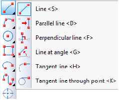
Attention: the automenu may display any of the encapsulated option icons in the given position. Usually this is the icon of the last used option among the encapsulated set.
In the Sketch command, nested icons are used when grouping actions aimed at creating a certain group of elements, for example: creation of segments, arcs, circles.
On the screen you will see the cursor in the form of a small square. Move the cursor to the bottom right part of the intended main view, near the center of the drawing, and click ![]() . The first point of the segment will be set, to which the dynamic “rubber thread” cursor will be attached, displaying the position of the created segment. In this case, the coordinates of the first point of the created segment will be recorded in the parameters window.
. The first point of the segment will be set, to which the dynamic “rubber thread” cursor will be attached, displaying the position of the created segment. In this case, the coordinates of the first point of the created segment will be recorded in the parameters window.

When building, it is necessary to take into account that space will be required along the edges of the drawing later on for dimensioning.
Move the cursor up. Note that in the parameters window, the coordinates of the cursor and its offset relative to the first point of the segment are tracked. We can use the parameters window to specify the exact position of the end of the segment. You can set the location of the second point of the segment in several ways: in Cartesian coordinates, indicating the absolute coordinates of the second point of the segment (X, Y), in Cartesian coordinates, indicating the offset of the second point relative to the first (dx, dy), in polar coordinates (L, A) or a combination of these methods.
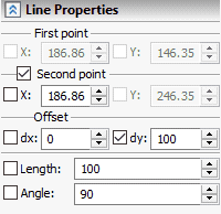
Define the second point of the segment, specifying its offset relative to the first point. Set the value of the “dx” parameter to zero, and for the “dy” parameter set the value to 100. At the same time, the absolute coordinates of the second point of the segment will be automatically entered in the “X” and “Y” parameter fields and the flag next to these parameters will be checked. Selecting the flag will prevent changing the corresponding coordinates when moving the cursor in the drawing field. The specified location of the second point of the segment will be shown on the screen.

To finish entering the coordinates of the second point, press <Enter> or ![]() , in the drawing field. This will create the first segment. Move the cursor to the left and set the length of the segment to 150. A circle with a radius of 150 mm will appear. Along the circle the second point of the segment will move, following the cursor.
, in the drawing field. This will create the first segment. Move the cursor to the left and set the length of the segment to 150. A circle with a radius of 150 mm will appear. Along the circle the second point of the segment will move, following the cursor.
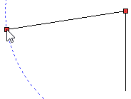
Find the position at which the perpendicular binding will appear. If the binding to the first segment does not work, then first move the cursor to the first segment, thus marking the line to which you want to look for bindings. Next, move the cursor to the left and find the position of the perpendicularity of the two segments and press <Enter> or ![]() .
.
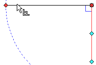
Next, move the cursor down and find the position at which the perpendicularity to the upper segment will be enabled and horizontal alignment to the lower point of the right segment. If the bindings to the segments are not found, then hover over the segments sequentially with the cursor. Once the necessary position of the second point of the third segment has been found, press <Enter> or ![]() .
.
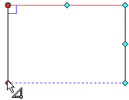
Move the cursor to the right, to the lowest point of the first line. The binding to the end points of the graphic line will be activated. Press <Enter> or ![]() . After that, you are still in the sketch creation command in continuous line input mode. The next step is to round the corner of the plate. To do this, select the Fillet option.
. After that, you are still in the sketch creation command in continuous line input mode. The next step is to round the corner of the plate. To do this, select the Fillet option.
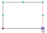
![]() <Shift+B> Fillet
<Shift+B> Fillet
This option is nested and may not be displayed in the automenu. It may be found in the group list (see the description above). The option is always visible in the Ribbon.
After accessing the option, the parameters window will change its appearance. Now you can set the required rounding radius. Set the radius value to 31 and make sure that the Trim Initial Lines flag is enabled.

Now it remains to choose two segments using ![]() . At the intersection of the sections it is necessary to construct a given round. In our case, this is the upper and rightmost segments of the plate. After selecting the last segment, rounding will occur, and the excess parts of the segments will be automatically cut off.
. At the intersection of the sections it is necessary to construct a given round. In our case, this is the upper and rightmost segments of the plate. After selecting the last segment, rounding will occur, and the excess parts of the segments will be automatically cut off.

Now we will draw the image of a conic hole on the main view. To do this, we construct two axial lines, thereby determining the exact center of the circles. Set the option:
![]() <S> Line
<S> Line
To create center lines, you should set the appropriate line type. In addition to the type of lines, you should also specify the protrusion of lines at the beginning and at the end. Set the dash-dotted line type in the parameters window or in the graphic line parameters dialog. The dialog can be called via the option:
![]() <P> Set Graphic line Parameters
<P> Set Graphic line Parameters
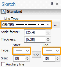
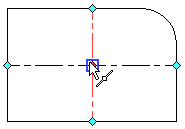
Move the cursor to the left segment of the image so that it binds to the middle of the segment. As soon as the binding will be enabled, the corresponding tooltip and icon will appear. Clicking ![]() to determine the first point. Move the cursor along the perpendicular from the left segment to the right segment, and stop it when the binding Point on Graphic line is triggered, as shown in the figure. Click
to determine the first point. Move the cursor along the perpendicular from the left segment to the right segment, and stop it when the binding Point on Graphic line is triggered, as shown in the figure. Click ![]() to create a centerline.
to create a centerline.

Since you work in the mode of continuous input of lines, then the next segment will be built from the last point. You do not need further construction from this point, so click ![]() .
.
In the same way, build a vertical centerline starting at the bottom segment.

Now create circles. First, set the main line type of the graphic line in the command parameters by calling the dialog box using the <P> option, or in the parameters window. Also replace the line end type with a regular one. Then select the option:
![]() <O> Circle by center
<O> Circle by center
This option is also nested and may not be displayed both in the Ribbon and in the automenu. It may be found in the group list.
After calling this option, move the cursor to the intersection of the two center lines. One of the many bindings at this point will appear, for example, as in this case, the middle of the vertical axis. Click ![]() . A dynamically changeable circle appears on the screen.
. A dynamically changeable circle appears on the screen.
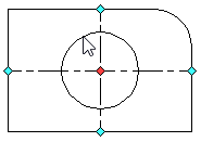
In the parameters window, set the value of the radius of the small circle of the conical hole to 25, and press the <Enter> button. The circle is fixed on the screen. Without leaving the option of creating a circle, build a circle with a radius of 35 mm. Thus, the construction of the main view of the detail can be considered complete.
Now we will construct the left view. To do this, set the mode for creating segments using the option ![]() . Move the cursor to the right side of the drawing and position it so that the horizontal link with the point lying on the top segment of the main view is activated and click
. Move the cursor to the right side of the drawing and position it so that the horizontal link with the point lying on the top segment of the main view is activated and click ![]() .
.
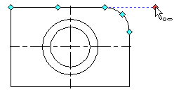
In the parameters window, set the length to 35 and for the second point of the segment lying on the circle, find the binding of horizontality. Press <Enter> or ![]() . A new segment will be fixed on the screen, and from the last created point there will be a “rubber thread” of the next segment. Next, move the cursor down vertically until the horizontal reference with points of the lower segment of the main view appears on the screen. If the binding does not appear, move the cursor to the lower segment and again find the positions with two bindings: verticality and horizontality. Click
. A new segment will be fixed on the screen, and from the last created point there will be a “rubber thread” of the next segment. Next, move the cursor down vertically until the horizontal reference with points of the lower segment of the main view appears on the screen. If the binding does not appear, move the cursor to the lower segment and again find the positions with two bindings: verticality and horizontality. Click ![]() and move the cursor to the left to create the next segment.
and move the cursor to the left to create the next segment.

Further, by analogy with the previous constructions, finish entering the rectangle.
The next step is to create the lines belonging to the conical hole in the left view. To do this, without leaving the line creation option, click ![]() to cancel segment creation from the last point. Next, move the cursor to the larger circle so that the binding algorithm “remembers” it, and then move the cursor to the right segment of the view to the left, and move it along this segment until the connection of the horizontal tangent with the larger circle is established. Click
to cancel segment creation from the last point. Next, move the cursor to the larger circle so that the binding algorithm “remembers” it, and then move the cursor to the right segment of the view to the left, and move it along this segment until the connection of the horizontal tangent with the larger circle is established. Click ![]() .
.
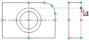
Now move the cursor to the smaller circle and then to the left segment of the view on the left and set it so that the reference is set by the horizontal tangent with the small circle. If another binding is determined, do not move the cursor for a while and wait until the list of all possible bindings appears. Use the mouse wheel or the cursor to select the necessary binding and click ![]() . Another option is to fix the binding with the <Space> key while the cursor is still close to the smaller circle.
. Another option is to fix the binding with the <Space> key while the cursor is still close to the smaller circle.
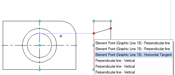
Next, click ![]() , to cancel the input of consecutive segments. In the same way, build the bottom line of the taper hole. Now, using the bindings already known to you, build the center line, do not forget to set the dash-dotted line type in the image line parameters (<P> option) or in the parameters window, and also change the type of line ending - to the line with protrusion.
, to cancel the input of consecutive segments. In the same way, build the bottom line of the taper hole. Now, using the bindings already known to you, build the center line, do not forget to set the dash-dotted line type in the image line parameters (<P> option) or in the parameters window, and also change the type of line ending - to the line with protrusion.
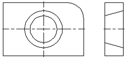
Let's switch to the top view. This view can be constructed in the same way as the left view, but for a more complete overview of the possibilities of the sketch, we will create it differently. Set the option:
![]() <Shift+P> Rectangle by two vertices
<Shift+P> Rectangle by two vertices
This option refers to the creating polygons group in the automenu and the group of rectangles in the Ribbon. If the icon for this option is not displayed in the automenu or in the Ribbon, then it can be called up using the corresponding icon for this group, which is marked with a black triangle (see description above).
The first vertex of the rectangle should coincide with the left vertical segment of the main view. Set the appropriate binding, click ![]() .
.
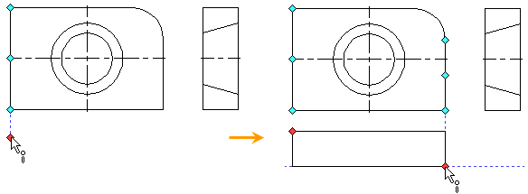
The second vertex must specify the thickness and length of the plate. Set the length by binding to the points of the right vertical segment of the main view. As before, if the bindings to the necessary lines of the drawing are not found, then you need to move the cursor to the line so that the algorithm of the bindings “remembers” it. You should set the plate thickness in the “dy” field of the parameters window, specifying the value -35.
Using the bindings of the vertical tangents to the circles, by analogy with the left view, we create the lines of the conical hole in the top view. Before building segments, you need to change the line type to dashed (line parameters <P>). For binding to a larger circle, it is convenient to use the snapping using the <Space> key.
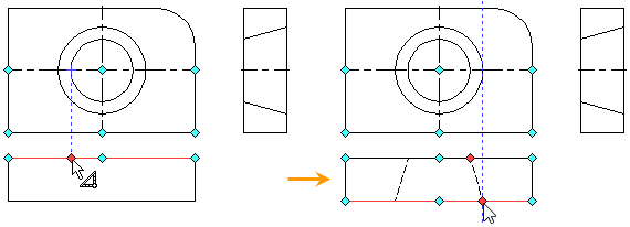
Create an axial line in the top view, to do this, replace the line type and the line end type (line parameters <P>).
It now remains to apply the hatching to the left view. Call the <H> Create Hatching command:
![]() <H> Create Hatching
<H> Create Hatching
Set the option:
![]() <A> Automatic contour search mode
<A> Automatic contour search mode
Then move the cursor to the upper part of the view on the left, and set it so that it is located in the center of the area to be shaded. Click ![]() and closed loop will be highlighted in color. Now move the cursor to the bottom of this view, and in the same way select the contour that you want to shade. After that click
and closed loop will be highlighted in color. Now move the cursor to the bottom of this view, and in the same way select the contour that you want to shade. After that click ![]() .
.
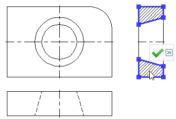
Next you should create dimensions on the drawing. Dimensions on the sketch are set in the same way as in the parametric drawing, in this case, instead of construction lines, you can select the graphic lines. This possibility was already described in the main method for creating drawings.

This completes the creation of non-parametric drawing. Further modification of its elements will not change the entire drawing. Each view in this case will have to be changed separately. Applying levels of visibility, using layers, disabling design elements, etc., work as usual.