Creating Parametric Drawing with Constrains |
  
|
Suppose we need to create a drawing:
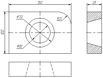
Moreover, it is necessary to make the drawing in such a way that it is controlled by the dimensions: changing the values of the dimensions should lead to a change in the entire drawing.
Call the «Sketch» command. In order to make the example more descriptive, disable all bindings.
Check that automatic creation of constraints is turned on.
![]()
Icon / Keyboard |
Filter toolbar |
|---|---|
|
Automatic creation of constraints |
Let's start by creating the main plate appearance. In the <SK> Sketch command, select the construction of a rectangle along two vertices.
|
<Shift+P> |
Rectangle on two vertices |
In an arbitrary place in the drawing, we create arbitrary sizes of rectangles: with the help ![]() we indicate two points. 8 constraints were automatically created: 4 Coincident constraints - at the intersection points of the line segments (the vertices of the rectangle), 2 Vertical constraints for vertical lines and 2 Horizontal constraints - for horizontal lines.
we indicate two points. 8 constraints were automatically created: 4 Coincident constraints - at the intersection points of the line segments (the vertices of the rectangle), 2 Vertical constraints for vertical lines and 2 Horizontal constraints - for horizontal lines.

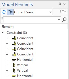
The list of restrictions can be seen in the "Model Elements" window.
Next, let's create a fillet. Rounding will be performed using the option:
|
<Shift+B> |
Rounding |
You can specify an arbitrary radius of the fillet, check box Trim Initial Lines option must be checked.
As in the previous example, with the help ![]() , we indicate two segments: the upper horizontal and the right vertical.
, we indicate two segments: the upper horizontal and the right vertical.

Automatically created 2 constraints Tangent at points of tangency of an arc and lines, and 2 constraints Coincident at points of tangency of lines and an arc. The coincidence point at the intersection of the continuation of the segments can be left or deleted. This point would make sense if you did not cut off the original curves, in this example it defines the intersection of the lines outside the drawing boundaries. Next, we will create circles of arbitrary radius at an arbitrary place in the drawing: one with a smaller radius than the second.
|
<O> |
Circle center and radius |
Let's create two more rectangles - one will define the left view, the other the top view. The principle of constructing rectangles is similar to that discussed earlier. The sizes and positions of the rectangles are arbitrary. As with the first rectangle, each rectangle has 8 constraints.
Let's set the parameterization of the already created constructions. We go to the «Constraints» command.

Keyboard |
Ribbon |
|---|---|
<SC> |
Draw > Constraints |
Icon |
Textual Menu |
|
Draw > Constraints |
The filter toolbar panel will display the bindings available for constraints. Let's include some of them that touch the lines of the image.
![]()
In this case, snaps are needed to select specific drawing elements (graphic lines and points) when creating constraints.
First, let's create a line relationship between different views of the drawing. To do this, we need to make sure that the horizontal lines of one kind always coincide with the horizontal lines of another, the same for vertical lines. This relationship can be set using the «Collinearity» constraint.
Icon / Keyboard |
Ribbon |
|---|---|
|
Constraints > Collinearity |
We select, with the ![]() , a pair of drawing lines in different views that should coincide, and then press
, a pair of drawing lines in different views that should coincide, and then press ![]() or <Ctrl+Enter>. It is worth noting that the constraints provide a fully variable parameterization and the order in which lines are selected does not affect the dependence of one line on another: the lines are equally interconnected.
or <Ctrl+Enter>. It is worth noting that the constraints provide a fully variable parameterization and the order in which lines are selected does not affect the dependence of one line on another: the lines are equally interconnected.

When you create Collinearity constraints, the selected lines are moved so that they are on the same line. When you move the lines, other relationships are preserved. So, for example, the coincidence of the extreme points of the rectangle segments is preserved due to the Coincident constraints, and due to the Vertical and Horizontal constraints, the parallelism and perpendicularity of the corresponding sides of the rectangles are also preserved.
To define the relationship of views, you need to create 4 Collinear constraints.
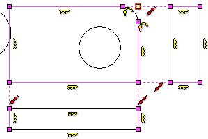
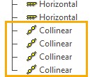
The number and type of restrictions can be viewed in the "Model Elements" window. When you select constraints in the "Model Elements" window, they will be highlighted in the drawing.
The next step is to position the circles. To do this, we will use the "Middle" constraint.
Icon / Keyboard |
Ribbon |
|---|---|
|
Constraints > Middle |
This restriction allows you to specify a point in the middle between two points or two segments (or lines). In our case, it is more convenient to set the center point of the circle as the middle between two segments: one constraint is between two vertical segments, and the second is between two horizontal main view.
Selecting the Middle constraint, specify the first vertical segment, then the second, and then the center point of the smaller circle. Thanks to object snaps ![]() , the center point of the circle will be found when you hover over the center of the circle. Finish entering constraint objects
, the center point of the circle will be found when you hover over the center of the circle. Finish entering constraint objects ![]() or <Ctrl+Enter>. By analogy, create a constraint between the horizontal lines and the center point of the circle.
or <Ctrl+Enter>. By analogy, create a constraint between the horizontal lines and the center point of the circle.

As a result, the two Middle restraints will define the position of the circle in the center of the plate. By analogy, you can determine the position of the second, larger circle, or you can simplify the definition of relationships and use the "Concentric" constraint.
Icon / Keyboard |
Ribbon |
|---|---|
|
Limitations > Concentric |
This constraint moves the center points so that they coincide. To create a constraint, you need to specify two circles with ![]() and finish entering constraint objects
and finish entering constraint objects ![]() or <Ctrl+Enter>.
or <Ctrl+Enter>.

As a result, two constraints, Middle and one Concentric, define the position of the circles in the drawing.
The next step is to create the tapered hole lines in the left view and define their position. The extreme points of the line segments representing the hole must always coincide with the vertical segments that indicate the contour of the slab. This relationship will be provided by the Coincident constraint. This constraint can be created automatically if, when constructing segments, their extreme points are snapped to vertical segments. In order for the snapping of the point to the image line to work during construction, enable the corresponding snapping on the snapping panel. By calling the command <SK> Sketch, activate the snapping.
The Automatic creation of constraints mode was enabled earlier. Let's create two arbitrary segments, the extreme points of which lie on the vertical segments of the slab contour. To construct line, select the option:
|
<S> |
Line |
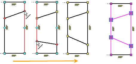
Hover the cursor over the first vertical segment, the snapping is triggered, with the help we indicate the first point of the segment, then move the cursor to the second vertical segment and indicate the second point of the segment. If the Continuous creation mode was enabled, then press, to cancel the construction of the next segment from the last point. By analogy, we construct the second segment. The vertical position of the end points of the tapered hole segments is not critical. The main thing is that due to snapping, 4 Coincident constraints are automatically created - for each of the two points of the tapered hole segments. We will define the required position of the end points of the tapered hole segments later.
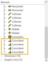
The number and type of restrictions can be viewed in the "Model Elements" window. When you select constraints in the "Model Elements" window, they will be highlighted in the drawing.
Let's put the axis on the main view. The principle of constructing the axes in general is similar to the just considered construction of segments of a tapered hole in the left view. For the vertical axis, it is necessary that the extreme points of the segment lie on the horizontal segments of the slab contour, for the horizontal - on the vertical ones. The vertical axis must be vertical, the horizontal axis must be horizontal. As we have already seen, the Coincident constraint is created automatically when the Point on Graphic Line snapping is triggered. If the Horizontal / Vertical snap ![]() is triggered when creating a line, the Vertical and Horizontal constraints will be created automatically. Turn on the necessary snapping on the snapping panel after calling the Sketch command.
is triggered when creating a line, the Vertical and Horizontal constraints will be created automatically. Turn on the necessary snapping on the snapping panel after calling the Sketch command.
|
Horizontal / Vertical |
Before creating line segments, change the line type and end type of the graphic line in the parameters of the graphic line <P> or in the parameters window.
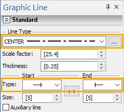
Let's start with the vertical axis. Hover the cursor over the upper horizontal segment and by pressing ![]() define the first point, then move the cursor down so that the "rubber thread" is vertical and snapping
define the first point, then move the cursor down so that the "rubber thread" is vertical and snapping ![]() works, bring the cursor to the lower horizontal segment and by pressing define the second point. As in the previous case, due to the snap trigger, 2 Coincident constraints were created, and due to the snap trigger
works, bring the cursor to the lower horizontal segment and by pressing define the second point. As in the previous case, due to the snap trigger, 2 Coincident constraints were created, and due to the snap trigger ![]() , the Vertical constraint was created. The horizontal position of the axis is not important, for precise positioning of the axis line in the center of the main view, you can use the Middle constraint or the Coincident constraint (between the axis line and the center of the circle).
, the Vertical constraint was created. The horizontal position of the axis is not important, for precise positioning of the axis line in the center of the main view, you can use the Middle constraint or the Coincident constraint (between the axis line and the center of the circle).

If the construction was carried out in the Continuous creation mode, then click ![]() to cancel the construction of the next segment from the last point.
to cancel the construction of the next segment from the last point.
Now let's place the axis line in the center of the view. We will do this using the "Coincident" constraint. Select the Coincident constraint.
Icon / Keyboard |
Ribbon |
|---|---|
|
Constraints > Coincident |
This constraint can be created between two points, or between a point and a line. Create a constraint between the axis line and the center point of the circle in the main view. To do this, after selecting the constraint, we indicate the axis line ![]() , and then the center point
, and then the center point ![]() . We finish creating the constraint:
. We finish creating the constraint: ![]() or <Ctrl+Enter>. The center point of the circle will be determined by snapping
or <Ctrl+Enter>. The center point of the circle will be determined by snapping ![]() . This snapping has already been enabled earlier on the snapping panel when calling the Constraints command.
. This snapping has already been enabled earlier on the snapping panel when calling the Constraints command.
As a result, the axis line is defined by 3 Coincident constraints (one of them was created manually to coincide with the center point of the circle) and 1 Vertical constraint.
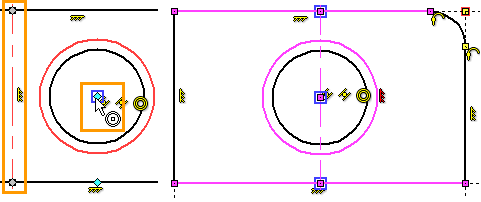
Let's create a horizontal axis by analogy.

All relationships between graphic lines in the main view are defined.
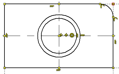
Now let's define the position of the tapered hole lines in the left view. It is necessary that each extreme point of the segments depicting a tapered hole in the left view should be on the same horizontal line with the corresponding intersection point of the circles with the vertical center line of the main view. Create points at the intersection of the circles with the vertical axis. Call the Sketch command and select the option to draw a point.
Keyboard |
Ribbon |
|---|---|
<SK> > <Shift+P> |
Drawing > Sketch > Point |
Icon |
Textual Menu |
|
Drawing > Sketch > Point |
At the intersection of the vertical axis with the circles, we put a point with ![]() . Due to the snapping
. Due to the snapping ![]() and the mode
and the mode ![]() , 2 Coincident constraints are automatically created for the constructed points. One constraint is between a point and a circle, the other between a point and an axis.
, 2 Coincident constraints are automatically created for the constructed points. One constraint is between a point and a circle, the other between a point and an axis.
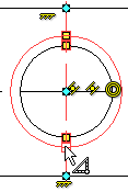
The next step is to define, using constraints, the relationship between each point of intersection of the circles with the centerline and the corresponding extreme point of the segments representing the tapered hole. The points must be in pairs on the same horizontal line.
To do this, you can use the Horizontal Alignment constraint.
Icon / Keyboard |
Ribbon |
|---|---|
|
Constraints > Horizontal Alignment |
Having chosen the considered constraint, we indicate the upper point of intersection of the large circle with the vertical axis, and in the left view we select the intersection point of the upper segment of the conical hole with the right vertical segment of the slab contour. We finish creating the constraint: ![]() or <Ctrl+Enter>.
or <Ctrl+Enter>.
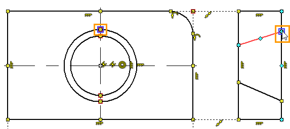
By analogy, we create constraints for all remaining pairs of points.
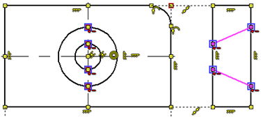
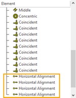
It is worth noting that when creating constraints, the extreme points of the segments may move, or the radius of the circles may change. This is due to the very principle of variational parametrization: all objects of constraints are equally dependent on each other. If there are no additional restrictions and both objects have degrees of freedom, then either of them can move.
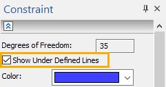
The presence of the degrees of freedom of the sketch lines can be viewed in the parameters window when calling the Constraint command. The number of degrees of freedom is specified for the entire drawing. If you set the Show Under Defined Lines checkbox, then lines with degrees of freedom will be highlighted in the selected color. The degree of freedom relative to the origin of the drawing is also taken into account.
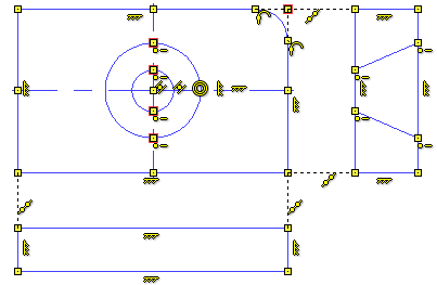
The next step is to draw the dotted lines representing the tapered hole in the top view. The construction principle will be similar to the construction principle for the lines in the left view.
•Let's construct two arbitrarily spaced segments, the extreme points of which lie on the horizontal segments of the slab contour. Due to snapping ![]() and mode
and mode ![]() , 4 constraints will be created Coincident between points and horizontal segments of the slab contour.
, 4 constraints will be created Coincident between points and horizontal segments of the slab contour.
•Create points at the intersections of the circles with the horizontal axis of the main view. Due to the snapping ![]() and the mode
and the mode ![]() , 8 Coincident constraints will be created. 2 constraints for each point: between a point and a horizontal axis, and between a point and a circle.
, 8 Coincident constraints will be created. 2 constraints for each point: between a point and a horizontal axis, and between a point and a circle.
•Using the "Vertical Alignment" constraint, set the relationship of points in the main view and in the top view.
Let's draw the line segments representing the conical hole in the top view. Having called the Sketch command, set in the parameters of the image line <P>, or in the parameters window, the line type is dashed, and the line end type is normal. Selecting the <S> Line option, place the cursor on the upper line of the slab contour and by pressing define the first point of the segment. Next, point to the bottom line, click - define the second point. By analogy, we construct the second segment. If the continuous input mode is on, you must press before drawing the second line segment.
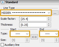
Thanks to snapping ![]() and mode
and mode ![]() , 4 Coincident constraints are automatically created - for each point of two lines.
, 4 Coincident constraints are automatically created - for each point of two lines.

Next, draw points at the intersection of the horizontal axis and circles <Shift + P> Point.
Set, using the Vertical Alignment constraint, the relationship between the points at the intersection of the circles with the horizontal axis and the extreme points of the segments representing the tapered hole in the top view.
Icon / Keyboard |
Ribbon |
|---|---|
|
Constraints > Vertical Alignment |
The principle of work with the constraint is completely similar to the example described above for the constraint Horizontal Alignment.
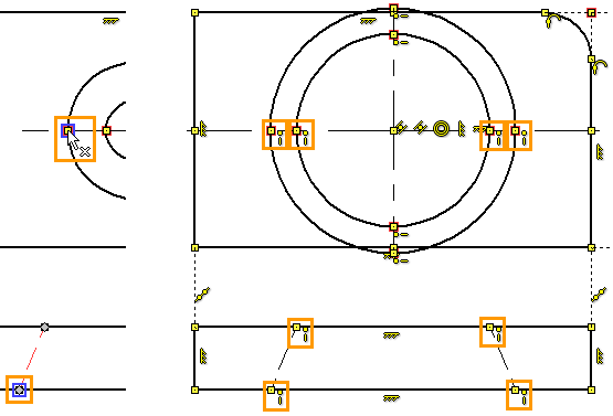
When creating constraints, the circles changed their radii and the lines remained in place. This situation, of course, contradicts the logic of the drawing, but does not contradict the mathematical model that we have created. Currently, the drawing model only establishes the relationship between the lines, but does not set specific values or limit values. There are special constraints (Fixed Length, Fixed Angle, Fix) and driving dimensions to specify the dimensions of the drawing. We will consider driving dimensions below.
When working with constraints, it is possible that the created relationships make the construction illogical. This is not an error in the sequence of constraint creation - constraints are completely variable and do not create any hierarchical sequence of relationships. Even if at some point the drawing took on an illogical form, you need to continue to specify the restrictions - gradually the drawing will take the required form. If, after creating constraints, the drawing takes a form that is inconvenient for further editing, you need to fix those elements for which movement in the process of creating constraints is undesirable. For this, there are anchor lines and dots constraints. In the future, unnecessary restrictions can be removed.
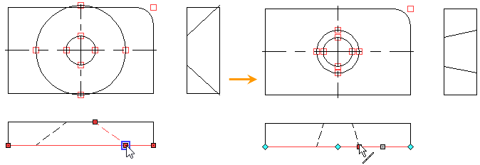
In this example, you can return the drawing to a logical view by editing the size of the circles. So that the constraints do not interfere with the snapping of the cursor to the drawing elements, the constraints can be hidden. On the "View" panel, click the icon ![]() .
.
Hover the cursor over the smaller circle, select it with ![]() , press it again
, press it again ![]() - go to its editing. The required radius of the circle is set by pressing
- go to its editing. The required radius of the circle is set by pressing ![]() .
.

Let's edit the second circle by changing the position of the point in the top view. Hover the cursor over a point, use ![]() to select it, press it again
to select it, press it again ![]() - go to its editing. Set the necessary point position by pressing
- go to its editing. Set the necessary point position by pressing ![]() . Note that the line on which the point is located also moves. This is because both a line defines a point and a point defines a line. Their coincidence is interconnected.
. Note that the line on which the point is located also moves. This is because both a line defines a point and a point defines a line. Their coincidence is interconnected.
Let's turn back the display of restriction icons in the drawing. To do this, click the icon ![]() on the "View" panel.
on the "View" panel.
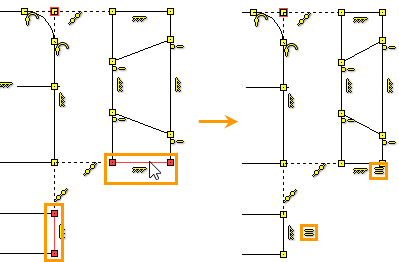
The slab thickness is shown in two views: top view and left view. So far, there is no connection between these dimensions. To make the thickness of the slab the same in the two views, create an "Equal Length" constraint.
Icon / Keyboard |
Ribbon |
|---|---|
|
Constraints > Equal Length |
We select the first segment by pressing ![]() , then the second
, then the second ![]() . We finish creating the constraint:
. We finish creating the constraint: ![]() or <Ctrl+Enter>.
or <Ctrl+Enter>.
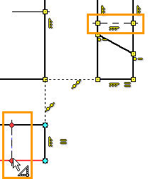
Let's plot the axes in the left and top view. We call the command <SK> Sketch and the option for constructing the segment <S>. Change the line type as we did before.

The principle of creating axes in the left and top views is completely similar to the principle of creating axes in the main view.
Hover the cursor over the contour line, snapping ![]() is triggered, by pressing
is triggered, by pressing ![]() we set the first point. Then on another line of the contour - the second point
we set the first point. Then on another line of the contour - the second point ![]() , and so that the Horizontal/Vertical snapping works. Thanks to the mode
, and so that the Horizontal/Vertical snapping works. Thanks to the mode ![]() , the Coincident constraints and the Horizontal or Vertical constraints (depending on the view) will be created.
, the Coincident constraints and the Horizontal or Vertical constraints (depending on the view) will be created.
As a result, centerlines will be created, which will only need to be correctly positioned. This can be done with various restrictions. The easiest way to use the Collinearity constraint is to create it between the centerlines in the main view and in the left and top views. Select the Collinearity constraint ![]() , use
, use ![]() to indicate the axis in the main view, then in the left view
to indicate the axis in the main view, then in the left view ![]() . We finish creating the constraint:
. We finish creating the constraint: ![]() or <Ctrl+Enter>. Then similarly for the top view.
or <Ctrl+Enter>. Then similarly for the top view.
This completes the creation of restrictions. All the relationships between the lines are defined.
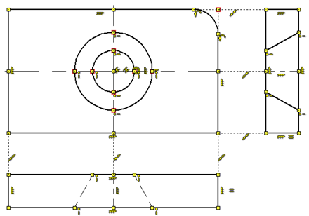
This drawing is completely parametric, and all relationships are equal: you can change any line of the drawing.
A drawing can be fully defined by placing driving dimensions on it.
Icon / Keyboard |
Ribbon |
|---|---|
|
Constraints > Driving Dimensions; Appearance > Dimension |
To create driving dimensions, you need to make the icon active in the ribbon. The icon is in the "Restrictions" group. Now all the dimensions that we create in the drawing will be control. To create dimensions, you need to use the standard design command <D> "Dimension".
If the dimension is set in Driving dimensions mode, then automatically, when creating it, you will be prompted to enter the dimension value.
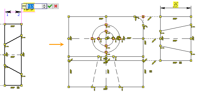
That the size of the manager is easy to understand from its background; unlike regular dimensions, driving dimension values are highlighted in the background. The background color indicates the various states of size and geometry in general.
•Yellow background - the drawing is not defined and has degrees of freedom
•Green background - the drawing is defined, there are no degrees of freedom. When the drawing is finished, it is recommended that the system be defined.
•Red background - the drawing has been redefined, i.e. there are sizes or limits that overlap or contradict each other. Or there is an error in setting the driving dimension value, when the entered value cannot be provided due to other restrictions.
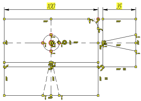
You can also adjust the distance between views with driving dimensions.

To prevent the size from being printed, you need to set it as Auxiliary. This option is available in the context menu. Click ![]() on the dimension, in the context menu select the Auxiliary option with
on the dimension, in the context menu select the Auxiliary option with ![]() . The size will change color to blue.
. The size will change color to blue.
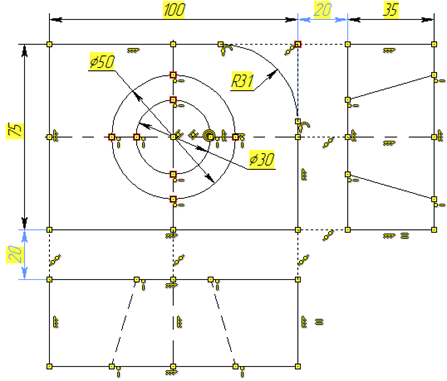
Now drawing lines cannot be changed by simple editing of the sketch: all keypoints are somehow dependent on driving dimensions. But the background color under the dimensions is yellow. This means there are degrees of freedom. This is due to the fact that the drawing is not defined relative to the origin. You can determine the position of the graphic lines by creating dimensions from the origin, or you can fix any point in the drawing. To do this, we will use the Fix constraint.
Icon / Keyboard |
Ribbon |
|---|---|
|
Constraints > Fix |
Select, using ![]() any point in the drawing and complete the entry of constraint objects:
any point in the drawing and complete the entry of constraint objects: ![]() or <Ctrl+Enter>.
or <Ctrl+Enter>.
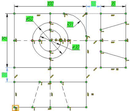
The dimension background turns green. This means that the drawing has no degrees of freedom and is fully defined.
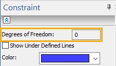
You can verify this in the parameters window of the Constraint command.
If the dimensions of the drawing need to be changed, then it is enough to click ![]() in the area where the value of the dimension is displayed and enter a new value.
in the area where the value of the dimension is displayed and enter a new value.
Let's apply hatching (<H> Hatch) and change the dimensions in such a way that the drawing completely repeats the dimensions of the drawing shown at the beginning of the example. To hide all auxiliary elements - you need to click the icon ![]() on the "View" panel, to hide the constraints - the icon
on the "View" panel, to hide the constraints - the icon ![]() .
.
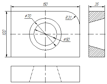
It should be noted that the proposed sequence of actions is not the only correct or the most rational one. This is primarily an example that aims to briefly show the various constraints and how they can be applied. With variational parameterization, there are many (if not infinitely many) options for sketching. The user himself can determine what constraints and sizes need to be created automatically, for this in the ribbon in the "Constraints" group you need to click the icon ![]() , try different combinations of constraints to create optimal relationships. The criterion for the optimal solution is simple: the fewer restrictions and dimensions are needed in order to fully define the drawing, the better.
, try different combinations of constraints to create optimal relationships. The criterion for the optimal solution is simple: the fewer restrictions and dimensions are needed in order to fully define the drawing, the better.