Sketch > Line |
  
|
The ![]() line by two points creating option is active by default, upon calling the Sketch command.
line by two points creating option is active by default, upon calling the Sketch command.
In the ribbon, as well as in the automenu of the Sketch command, options of straight line segments creation are grouped into a drop-down list. The presence of the drop-down list is indicated by the black triangle near an icon of an option displayed, when the list is folded. In order to unfold the list, either click ![]() a triangle
a triangle ![]() in the ribbon, or click and hold
in the ribbon, or click and hold ![]() on an icon of an option displayed, when the list is folded. This icon corresponds to an option used last in the current CAD session. When the Sketch command is launched, any option can be called via keyboard without unfolding the list.
on an icon of an option displayed, when the list is folded. This icon corresponds to an option used last in the current CAD session. When the Sketch command is launched, any option can be called via keyboard without unfolding the list.
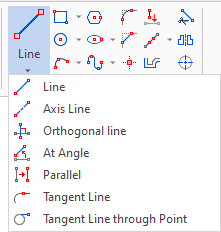
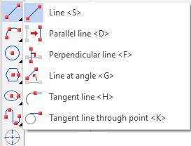
Line by two points
Icon |
Ribbon |
|---|---|
|
Draw > Sketch > Line > Line Remarks > Remarks > Line > Line Workplane > Sketch > Line > Line |
Keyboard |
Textual Menu |
<SK>><S> |
|
Automenu of the |
|
<S> |
Line |
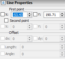
To create a simple line segment, you need to specify two points. Points can be set arbitrarily by pointing the cursor in the drawing window and clicking ![]() or by specifying the exact coordinates in the parameters window. Position of a first point is defined by absolute coordinates X and Y. Position of a second point may be defined by one of the following sets of parameters:
or by specifying the exact coordinates in the parameters window. Position of a first point is defined by absolute coordinates X and Y. Position of a second point may be defined by one of the following sets of parameters:
•absolute coordinates X and Y;
•offsets dx and dy from the first point;
•Length and Angle of the segment, where angle is measured counterclockwise from the horizontal direction.
When inputting values of parameters, you can use hot keys and checkboxes fixing values.
When creating a segment, you can select all available object snappings as its points.
Icon |
Ribbon |
|---|---|
|
Draw > Sketch > Line > Axis Line Workplane > Sketch > Line > Axis Line |
Axis is a line segment by two points with a dash-and-dot line type. The type cannot be changed.
Icon |
Ribbon |
|---|---|
|
Draw > Sketch > Line > Parallel Workplane > Sketch > Line > Parallel |
Keyboard |
Textual Menu |
<SK>><D> |
|
Automenu of the |
|
<D> |
Parallel line |
In this case, use the cursor to select ![]() a line, relative to which you want to create a parallel one. A dynamically movable straight line, parallel to the selected line, will appear on the screen. If continuous input of lines mode is enabled, then this straight line will be parallel to the last created line. You can refuse to select a segment by clicking
a line, relative to which you want to create a parallel one. A dynamically movable straight line, parallel to the selected line, will appear on the screen. If continuous input of lines mode is enabled, then this straight line will be parallel to the last created line. You can refuse to select a segment by clicking ![]() .
.
After specifying the initial line, you should specify the Distance to the new line and coordinates X and Y of its starting point. This can be done arbitrarily by moving the cursor and clicking ![]() at the necessary area of the drawing, or by typing exact values in the parameters window. When inputting values of parameters, you can use hot keys and checkboxes fixing values.
at the necessary area of the drawing, or by typing exact values in the parameters window. When inputting values of parameters, you can use hot keys and checkboxes fixing values.
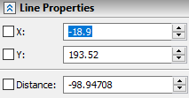
As you type in the Distance in the parameters window, the dynamic straight line gets fixed at a given distance from the initial line. The dynamic point attached to the cursor, which sets the start of the new line, will move along the dynamic line. Point's position is set by clicking ![]() . X and Y coordinates' input boxes in the parameters window are non-editable in this case.
. X and Y coordinates' input boxes in the parameters window are non-editable in this case.

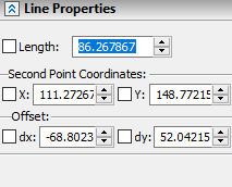
After defining the starting point of the new line, you need to define its ending point. A fixed line parallel to the original line will pass through the first point. The ending point of the new line can be set arbitrarily by moving the cursor along a straight line and clicking ![]() , or you can specify its position precisely in the parameters window. Position of the ending point may be defined by one of the following sets of parameters:
, or you can specify its position precisely in the parameters window. Position of the ending point may be defined by one of the following sets of parameters:
•Length of the line segment;
•absolute coordinates X and Y;
•offsets dx and dy from the starting point.
When inputting values of parameters, you can use hot keys and checkboxes fixing values.
Icon |
Ribbon |
|---|---|
|
Draw > Sketch > Line > Orthogonal Line Workplane > Sketch > Line > Orthogonal Line |
Keyboard |
Textual Menu |
<SK>><F> |
|
Automenu of the |
|
<F> |
Perpendicular Line |
The option allows to create a perpendicular only to straight lines. In this case, the perpendicular reference line is first selected, and then the position of the perpendicular line is specified. If the continuous line input mode is enabled, an infinite straight line will appear on the screen after selecting this option. The infinite line is perpendicular to the last created line and passes through its second point. This point will be the starting point of the new line. Move the dynamically moving point along the infinite line using the cursor and fix its position with the help of ![]() (or type in coordinates in the parameters window).
(or type in coordinates in the parameters window).
If it is necessary to create a perpendicular to another line or to the same line through other point, then you can decline the choice made by the system in the mode of continuous line input by clicking ![]() . A first click
. A first click ![]() will cancel the selection of the starting point of the line being created. A second
will cancel the selection of the starting point of the line being created. A second ![]() click will cancel the selection of the initial line and allow you to select the necessary line. When you select a line, an endless dashed line follows the cursor. The position of this line defines the position of the segment. With the help of
click will cancel the selection of the initial line and allow you to select the necessary line. When you select a line, an endless dashed line follows the cursor. The position of this line defines the position of the segment. With the help of ![]() you can fix the line and specify the first point of the segment (or set the coordinate of the point in the parameters window). After that, the second point of the segment moves along a straight line following the cursor. The position of the second point is specified using
you can fix the line and specify the first point of the segment (or set the coordinate of the point in the parameters window). After that, the second point of the segment moves along a straight line following the cursor. The position of the second point is specified using ![]() (or the length of the segment can be set in the parameters window). When inputting values of parameters, you can use hot keys and checkboxes fixing values.
(or the length of the segment can be set in the parameters window). When inputting values of parameters, you can use hot keys and checkboxes fixing values.

If you need to create a perpendicular at a specific point, then it is more convenient to use the Line (<S>) option and object snappings. This method allows you to create a perpendicular to any curve: circle, arc, spline, ellipse.
Example
Create line Perpendicular to Arc
A line perpendicular to the tangent of the given arc should be created.

To do this, move the cursor over the arc in the Line <S> mode. A dynamic point will appear moving along the arc in accordance with movement of the cursor. By pressing ![]() we define the position of the point, from which we will create the segment. After that, the position of the cursor defines the coordinates of the second point of the segment. You can change the angle of the segment by moving the cursor. We find the position in which the perpendicular snapping is automatically detected. The tangent direction will be indicated with a thin dashed line. At the point of tangency, a perpendicularity sign will be indicated, and the icon
we define the position of the point, from which we will create the segment. After that, the position of the cursor defines the coordinates of the second point of the segment. You can change the angle of the segment by moving the cursor. We find the position in which the perpendicular snapping is automatically detected. The tangent direction will be indicated with a thin dashed line. At the point of tangency, a perpendicularity sign will be indicated, and the icon ![]() will appear next to the cursor. By leading the cursor along the perpendicular line we define the length of the segment. Finish the construction by pressing
will appear next to the cursor. By leading the cursor along the perpendicular line we define the length of the segment. Finish the construction by pressing ![]() . The exact length of the segment can be entered in the corresponding input box of the parameters window.
. The exact length of the segment can be entered in the corresponding input box of the parameters window.
Icon |
Ribbon |
|---|---|
|
Draw > Sketch > Line > At Angle Workplane > Sketch > Line > At Angle |
Keyboard |
Textual Menu |
<SK>><G> |
|
Automenu of the |
|
<G> |
Line at Angle |
This segment is constructed similarly to the perpendicular one, with the only difference that you can set the required angle in the parameters window.
A button ![]() in the parameters window will allow you to flip the direction of the angle measurement relative to the selected segment.
in the parameters window will allow you to flip the direction of the angle measurement relative to the selected segment.
When inputting value of length, you can use hot key and checkbox fixing value.

Icon |
Ribbon |
|---|---|
|
Draw > Sketch > Line > Tangent Line Workplane > Sketch > Line > Tangent Line |
Keyboard |
Textual Menu |
<SK>><H> |
|
Automenu of the |
|
<H> |
Tangent Line |
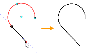
This option creates a tangent straight line segment at an ending point of an arc or spline. First, with the help of ![]() , you need to select an arc or spline. After that, an auxiliary infinite line is displayed on the screen, tangent to an arc or spline at the ending point. The ending point, to which the cursor was closer at the moment of selecting the element, is used. If the spline is closed, then the first point of the spline is used. This point will be the starting point of the resulting segment. In the continuous sketch creation mode, if the last created element is an arc or a spline, it gets automatically selected as the source for tangent line creation - the tangent line starts at its ending point. The dynamic preview of the ending point of the segment will follow the cursor along the tangent line. Set the desired position of the ending point and press
, you need to select an arc or spline. After that, an auxiliary infinite line is displayed on the screen, tangent to an arc or spline at the ending point. The ending point, to which the cursor was closer at the moment of selecting the element, is used. If the spline is closed, then the first point of the spline is used. This point will be the starting point of the resulting segment. In the continuous sketch creation mode, if the last created element is an arc or a spline, it gets automatically selected as the source for tangent line creation - the tangent line starts at its ending point. The dynamic preview of the ending point of the segment will follow the cursor along the tangent line. Set the desired position of the ending point and press ![]() or <Enter> to finish the input. When specifying the position of the ending point, you can use object snappings, or type in the exact value of segment's length in the parameters window. When inputting value of length, you can use hot key and checkbox fixing value.
or <Enter> to finish the input. When specifying the position of the ending point, you can use object snappings, or type in the exact value of segment's length in the parameters window. When inputting value of length, you can use hot key and checkbox fixing value.
Icon |
Ribbon |
|---|---|
|
Draw > Sketch > Line > Tangent line through point Workplane > Sketch > Line > Tangent line through point |
Keyboard |
Textual Menu |
<SK>><K> |
|
Automenu of the |
|
<K> |
Tangent line through point |
With this command, you can construct a tangent segment at any point of any graphic line curve (circle, arc, ellipse, spline).
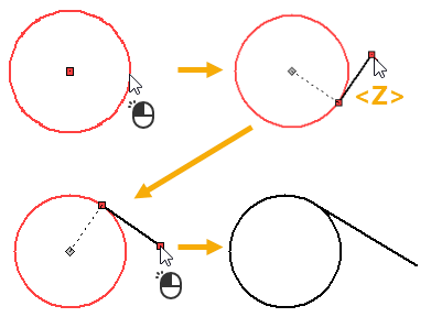
First, upon calling the command, you should select a curve using ![]() . The selected object will be highlighted. When selecting an arc, you may construct a tangent line to any point of the full circle or full ellipse the arc belongs to. Full circle or full ellipse gets indicated by auxiliary lines. Upon selecting a curve the preview of the resulting line appears. The preview gets dynamically updated in accordance with the position of the cursor. The resulting line is defined by two endpoints: one point coincides with the position of the cursor, other point (point of tangency) is defined by constructing a tangent to the selected curve passing through the cursor position. Upon selecting any curve, except an open spline, for each cursor position there are two possible tangency variants. The applied tangency variant is selected by the system arbitrarily. You can switch tangency variant, if necessary, by pressing the <Z> key. Set the desired configuration of the resulting line and press
. The selected object will be highlighted. When selecting an arc, you may construct a tangent line to any point of the full circle or full ellipse the arc belongs to. Full circle or full ellipse gets indicated by auxiliary lines. Upon selecting a curve the preview of the resulting line appears. The preview gets dynamically updated in accordance with the position of the cursor. The resulting line is defined by two endpoints: one point coincides with the position of the cursor, other point (point of tangency) is defined by constructing a tangent to the selected curve passing through the cursor position. Upon selecting any curve, except an open spline, for each cursor position there are two possible tangency variants. The applied tangency variant is selected by the system arbitrarily. You can switch tangency variant, if necessary, by pressing the <Z> key. Set the desired configuration of the resulting line and press ![]() to finish its creation. When specifying the position of the endpoint snapped to the cursor, you can use object snappings, or type in the exact coordinates via keyboard in the parameters window. When typing values of coordinates, you can use hot keys and checkboxes fixing values. You cannot specify a point inside a closed curve (including full circle or ellipse the selected arc belongs to), because in this case the tangent line cannot be constructed.
to finish its creation. When specifying the position of the endpoint snapped to the cursor, you can use object snappings, or type in the exact coordinates via keyboard in the parameters window. When typing values of coordinates, you can use hot keys and checkboxes fixing values. You cannot specify a point inside a closed curve (including full circle or ellipse the selected arc belongs to), because in this case the tangent line cannot be constructed.
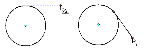
Alternatively, a tangent segment can be created in any point of any curve using the basic (Line <S>) option. It can be done in one of the following ways:
•Constructing a tangent segment, using the automatic tangency detection
By default, the Automatically find tangents when creating line segments option is enabled (Options > Constraints and Dimensions > Infer Constraints). In result, upon snapping a first point of a segment to an arbitrary point on a curve, the special indicator appears around the point ![]() . Then, if you move the cursor in a direction close to the direction of tangency to the curve at this point, then the tangent segment creation mode is activated, similar to the one described above. If you move the cursor in any other direction, the tangent segment creation is not activated, but you still can create a tangent segment using object snappings (see below). Moreover, the tangent segment creation is not activated, if the first point is snapped to one of the characteristic points of a curve.
. Then, if you move the cursor in a direction close to the direction of tangency to the curve at this point, then the tangent segment creation mode is activated, similar to the one described above. If you move the cursor in any other direction, the tangent segment creation is not activated, but you still can create a tangent segment using object snappings (see below). Moreover, the tangent segment creation is not activated, if the first point is snapped to one of the characteristic points of a curve.
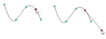
•Constructing a tangent segment, using object snappings
If you place the first point of a segment outside a curve, using the ![]() Horizontal/Vertical tangent snapping, and place the second point on the curve, using the
Horizontal/Vertical tangent snapping, and place the second point on the curve, using the ![]() Point on Graphic Line snapping, then a horizontal or vertical tangent segment will be created.
Point on Graphic Line snapping, then a horizontal or vertical tangent segment will be created.
If you place the first point on a curve, using the ![]() Tangent to Graphic Line snapping, and place the second point outside the curve, using any method, then an arbitrary angled tangent segment will be created.
Tangent to Graphic Line snapping, and place the second point outside the curve, using any method, then an arbitrary angled tangent segment will be created.
