Example of Worksurface Creation |
  
|
Example of Worksurface Creation |
|
Example 1
To understand how worksurfaces are created and used, let's review a brief example. Suppose, we need to wrap a text on a cylindrical body face.
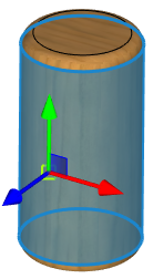
To create a worksurface, call the Worksurface command and select cylindrical face of the source body in the 3D window.


The command's parameters window displays the parameters of the surface being created. Those do not need to be changed.
The Offset parameter defines the difference between the source face radius and that of the surface being created. The required “0” value is already set by default.
The Units parameter defines, what units will be applied along the U-axis. The default setting Linear should also be left unchanged.
To create the worksurface, just click ![]() . As a result, a cylindrical worksurface will be created, which coincides in the radius and position in the space with the source face, or, rather, with its geometrical surface.
. As a result, a cylindrical worksurface will be created, which coincides in the radius and position in the space with the source face, or, rather, with its geometrical surface.

By now the worksurface is created. Now we need to create the 3D profile-text on it. To do that, select the created surface and call its context menu by right-clicking ![]() . In the menu select the command Draw On Workplane. A separate window will open with the 2D drawing page, corresponding to the selected worksurface.
. In the menu select the command Draw On Workplane. A separate window will open with the 2D drawing page, corresponding to the selected worksurface.
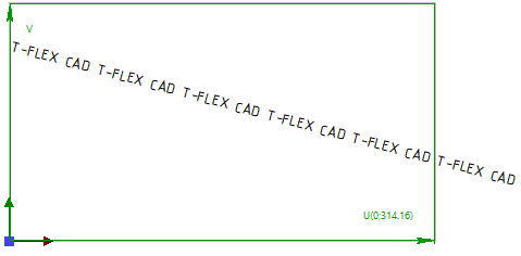
A box will be marking the parametric 2D region of a worksurface on the page. Let's create the required text on the 2D page. Finish drawing on the active worksurface. Upon leaving the mode of drawing on the active worksurface, a 3D Profile will be automatically created based on the 2D text.

What is left is to extrude the 3D profile to the required height and perform a Boolean addition of the resulting text and the source cylinder.
Example 2
Let's see another example. In it, we need to apply a text on a cylindrical-shape plate while maintaining a specified offset distance from the plate borders.

In this example, two worksurfaces will be used. We will construct the first one by the cylindrical face of the source body. On it, let's create the 3D profile of the plate contour. We will construct the second worksurface by the outer face of the plate. The 3D profile-text will be created on the latter worksurface.
The difference of this example from the previous one is that in this case we need to know how precisely the worksurfaces and their source faces are positioned relative to each other. Otherwise, it will be impossible to precisely position the plate on the cylindrical body, and the text – on the plate. To precisely position the worksurface, one can use an additional 3D point. The surface coordinate origin will be placed at that point. Let's create a 3D node on the face of the source body where the lower-left corner of the plate shall be positioned.
Next, as in the previous example, you need to call the Worksurface command and create a surface based on a cylindrical face.
The parameters of the created worksurface, set by default, will not be changed again. But before confirming the creation of the surface, we will include the option in the auto menu:
|
<1> |
Select starting point |
Using this option, we will select the 3D node created earlier.

The surface coordinate origin will be positioned where the node projects (maps) on the surface. After selecting the 3D node, the worksurface creation can be finalized by clicking ![]() . After that we will select the worksurface and call from its context menu the command Draw On Workplane. As in the previous example, after calling the command, a separate window will open with the 2D drawing page corresponding to the selected worksurface. A box on the page will be marking the parametric 2D region of the worksurface. The worksurface coordinate origin (the lower-left corner of the box) corresponds to the 3D node that defines the lower-left corner position of the would-be plate.
. After that we will select the worksurface and call from its context menu the command Draw On Workplane. As in the previous example, after calling the command, a separate window will open with the 2D drawing page corresponding to the selected worksurface. A box on the page will be marking the parametric 2D region of the worksurface. The worksurface coordinate origin (the lower-left corner of the box) corresponds to the 3D node that defines the lower-left corner position of the would-be plate.
By accepting the lower-left corner of the box as the base point, let's create the necessary 2D constructions to create the plate contour. To create a 3D profile, you need to apply a contour in any convenient way.
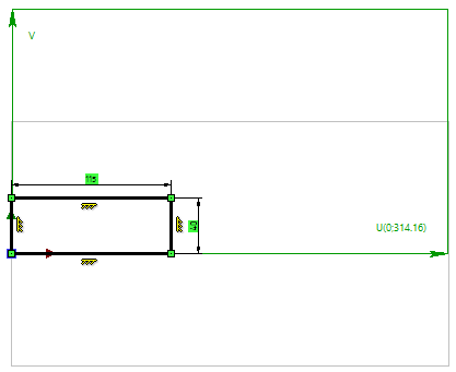
Finish working in the mode of drawing on the active worksurface. Upon exiting the mode of drawing on the worksurface, the plate's 3D profile will be automatically created. The plate body is created by extruding the resulting 3D profile.


To create text on the plate, we will construct a second worksurface. The construction will be similar to the previous cases. To define the surface coordinate origin, select one of the vertices (the lower-left one) of the plate's upper face.

After creating the second worksurface, we will go into the mode of drawing on it (the command Draw On Workplane in the surface's context menu). On the worksurface page, mark the plate boundaries. After that, apply 2D text at the desired position on the plate.


Next, the 3D profile on the worksurface is created based on the 2D text. The profile is extruded, and a Boolean addition with the plate body is performed. In the described example, we relied on a 3D point selection as the worksurface origin to precisely position the 3D profile contour on the worksurface. The same goal could be achieved using a different method. Working in the mode of drawing on the active worksurface (the command Draw On Workplane in the context menu) is mostly analogous to working in the respective mode on a workplane. The only difference is that one can draw on a workplane both in 2D window and directly in the 3D window. For a worksurface, only the mode of drawing in the 2D window is available. Besides that, all other functions of this mode are supported for a worksurface, including the capability of projecting (mapping) a 3D point on the active plane/surface.
In our example, one could have skipped selecting additional 3D nodes as the origin for worksurfaces, but rather have them mapped in the drawing-on-surface mode. After that, it is possible to create all underlying construction for the 3D profile contours based on the created 2D nodes-the projections.