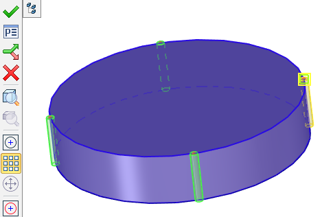
Hole Orientation |
  
|
By default, all new created holes are placed by the system in such a way, that the axis of each hole (X-axis of the hole template coordinate system) is directed along the normal to the base face at the attachment point. The orientation of the hole cross section is set by the system arbitrarily. (This is the angle of the hole cross section rotation about the Y-axis of the hole coordinates.)
If necessary, you can modify orientation of each hole in a set separately.
Orientation is specified by specifying the direction and rotation for each hole. The options become available when you activate the Orientation checkbox on the Position and Orientation tab.
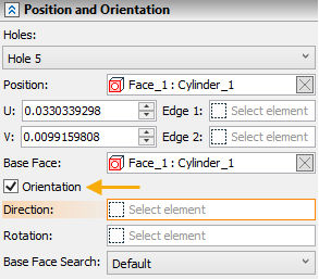
A hole's orientation can be modified in one of the two ways:
By auxiliary LCS
A specified LCS is used for defining the direction of the axes of the coordinate system of the hole (existing in its template). The hole is rotated in such a way that its coordinate system axes all get aligned with the direction of the respective axes of the selected LCS;
Defining direction by LCS:
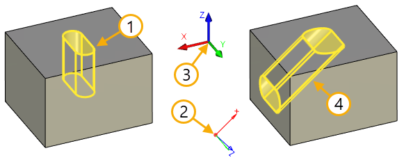
1. Original hole direction
2. LCS that defines the direction of the hole
3. Global coordinate system
4. Hole direction according to LCS
Defining rotation by LCS:
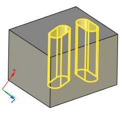
It is also possible to orient all the holes of the set according to one LCS.
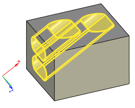
By 3D nodes
In this case, the hole's orientation and the angle of rotation about its axis are defined separately. You can modify just one of these parameters, for example, only rotation of the hole about the axis, in order to turn a non-round hole about its axis. In this case, the axis itself can be left unchanged (in the system default position).
When using a 3D node for orienting the hole axis, the axis will be directed from the hole attachment point to the 3D node. When specifying rotation of the hole by a 3D node, the Y-axis of the hole coordinate system will be turned so as to point at the selected node.
Defining direction by 3D Node:
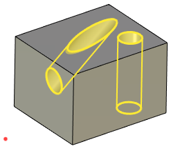
Defining rotation by 3D Node:
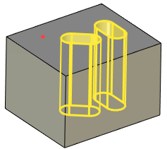
Base face search
If necessary, in the Search Face Base drop-down list, you can explicitly specify in relation to which base face the hole should be created.
There are 3 options available:
•Default
•Nearest
•First
If the Default option is selected, the hole can only be created based on 3D nodes belonging to the selected face.
The Nearest and First options allow you to create a hole based on 3D nodes that do not belong to the selected face.
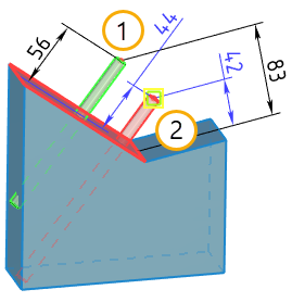
The Nearest option allows you to select the nearest base face to the selected 3D node. To create a hole on the nearest base face, you need to do the following:
1. Run the Hole command.
2. In the Search Face Base drop-down list, select the Nearest option.
3. Specify the 3D node on which you want to create a hole.
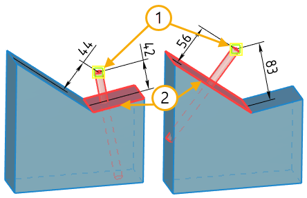
1. 3D nodes
2. Nearest base faces
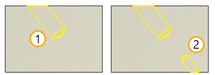
The First option is used to create a hole relative to the base face on which the first hole was created. This option can only be used in the mode of adding additional holes. To create a hole in this way, you need to do the following:
1. Run the Hole command.
2. Select the first node to create the first hole.
3. Without leaving the command, select the option First.
4. Specify the 3D node on which to create the next hole.
1. The first 3D node to create the first hole using the Nearest option
2. The second 3D node on which the second hole is created using the First option
Any hole can be created as coaxial (using the same axis) with an arbitrary cylindrical or conic face. A hole can also be created coaxial with an existing round hole.
The location of the base face should permit creating a coaxial hole. For example, when creating a hole coaxial to another hole, the two holes may not be placed on the same face.
The axis directions of the new hole will coincide with that of the source face.
1. Original hole
2. Coaxial hole
Create Holes With Specifies Direction
Nodes for the holes are located on the boundary of two or more faces. It is required to create holes on the nodes according to certain direction. Since the system cannot automatically determine the direction, it selects the first appropriate solution. However, the user can independently set the direction by performing the following sequence of actions.
In this example, we will build an array of holes using the nodes created on the edge of the body. The nodes are already created.
Step 1. Select the face for the hole. The face will define the direction for the hole.
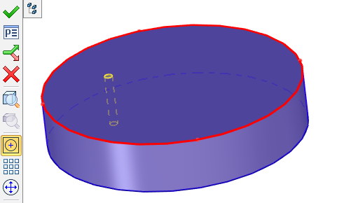
Step 2 – Select A: Enter hole center command and select one of the nodes for which holes should be created. The system will construct holes according to the selected face.
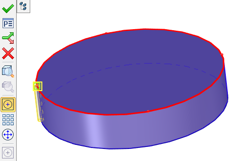
Step 3 - Select the rest of the array.
