Main Concepts of Body Taper |
  
|
For creating a body taper, first of all it is necessary to indicate a tapered body itself, a parting body, the sets of “top” and “bottom” fixed edges of the tapered body, taper direction and angle.
Taper Direction
Taper direction is an oriented in space vector, relative to which the taper angles of the faces will be measured.
Taper direction vector can be defined by two methods:
•by one 3D object whose geometry can define a vector;
•by two 3D points defining the start and end points of a vector.
Parting Body
A parting body is used for dividing the original body into two parts, each of which can be tapered individually. When tapering faces at both sides from the parting body, a two-sided taper is created. When tapering faces located at one side from the parting body, a one-sided taper is created.
|
|
One-sided raper |
Two-sided taper |
Both surface and solid bodies can be used as a parting body. In most cases, a surface body is used as a parting body. After executing the operation, a parting body is remained in the 3D scene.
The parting body may not have through holes. Additionally, the parting body must be large enough to fully intersect the target body in the taper direction.
If a solid was selected as the parting body, then use of the Body Taper operation will result in one body obtained by merging the tapered and the parting body.
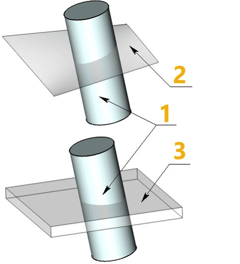
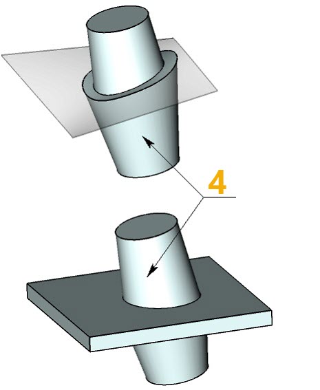
1 - Source body
2 - Parting surface body
3 - Parting solid
4 - Operation result
The source body itself can be used as the parting body. On the figure below, an isoclinal line of the faces of the original body was selected as the source edges for creating the taper. The original body itself serves as the parting body.
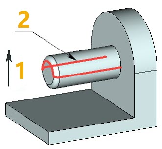
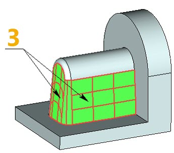
1 - Taper direction
2 - Isocline of source body faces
3 - Added material
Fixed Edges/Faces
For creating two-sided tapers of a body it is required to specify two sets of edges: top edges and bottom edges.
The so-called “top” and “bottom” sets of base edges are respectively those located above and below the parting body, with respect to the taper direction. The edges define the faces for which a taper needs to be created, and also define the fixed lines of these faces.
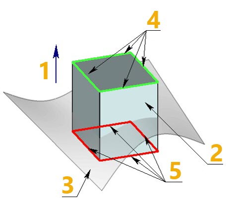
1 - Taper direction
2 - Source body
3 - Parting body
4 - Top set of edges
5 - Bottom set of edges
It is possible to select only one set of fixed edges (“top” or “bottom”). In this case, a one-sided taper will be created.
Instead of source edges, the user can specify the source faces themselves. For example, when creating a body taper, it might be impossible to select base edges of the “top” and “bottom” sets. Those edges might either not exist, or have the geometry that would not allow creating a body taper. In this case, for creating a taper the user indicates the sets of source faces based on which the virtual edges for constructing the body taper are defined. If, for example, a face was selected as “top”, then the command will automatically find the uppermost point on this face with respect to the taper direction. A virtual edge is defined at this point, passing tangentially to the edge of the selected face and perpendicular to the taper direction vector.

1 - Taper direction
2 - Parting body
3 - Specified top face
4 - Top point on the top face in taper direction
5 - Virtual edge
Taper Angle
Taper angle is specified separately for the “top” and “bottom” set of edges, i.e. for the “top and “bottom” faces. Within each set, all faces will have identical taper angle.