Create Body Taper |
  
|
Selecting source body
The default mode of selecting the source body is activated automatically upon entering the Body Taper operation:
|
<S> |
Select source body |
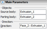
This source body can be selected either in the scene or in the 3D model tree. After selecting the source body, the parameters window will display the respective operation of the source body.
Selecting parting body
Upon selecting the source body, the system proceeds to the mode of selecting the parting body. To enable selection of a surface or sheet as a parting body, the following options are provided in the command automenu:
|
<A> |
Select parting body |
|
<H> |
Select parting surface body |
When using one of those options for selecting the parting body, the selector is tuned up accordingly. For example, in the surface body selection mode, the following parting objects can be selected: a face, a 3D profile, an operation-surface. Moreover, filters for choosing the objects can be also customized with the help of the filter toolbar.
In the solid body selection mode, only objects with solid geometry can be selected for parting.
The name of the object used as the separating body is displayed in the Parameters window.
Defining taper direction
The next step in the operation creation is selecting an element defining the taper direction. This can be done by the option:
|
<D> |
Set tapering direction |
As common across other operations, the option for selecting the taper direction allows selection of various 3D elements capable of defining a directional vector. The direction-defining object is displayed in the parameters window.
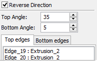
To change the taper direction to the opposite, check the parameter Reverse Direction.

Alternatively, the taper direction can be defined by two 3D points. The following options are provided for this purpose:
|
<1> |
Select first point of tapering direction |
|
<2> |
Select second point of tapering direction |
Selected elements are displayed in the Parameters window.

To cancel the direction selection, use the option:
|
<K> |
Cancel direction selection |
Selecting fixed edges
Selection of the set of edges is done directly in the 3D window. To create a one-sided taper, select just the top set of edges. For the two-sided taper, additionally select the bottom set of edges. To do this, use the following options:
|
<T> |
Select top edges |
|
<B> |
Select bottom edges |
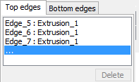
Each selected edge will be added to the list of edges in the parameters window. Switching between selecting the top and bottom sets of edges can be done either by the automenu options or by clicking the respective tabs in the parameters window dialog. To remove an edge from the list, select it in the list, and then press the Delete button or <Del> key.
Options ![]() and
and ![]() can be used in combination with the mode of selecting a sequence of smoothly connected edges, which can be activated by the option:
can be used in combination with the mode of selecting a sequence of smoothly connected edges, which can be activated by the option:
|
<G> |
Smooth edge chain selection mode |
Let us define a sequence of smoothly connected edges as a set of edges forming closed or non-closed continuous curve which does not have sharp turns (the first derivative is continuous).
When using the given mode, all edges capable of making a smooth sequence with the chosen edge are automatically picked.
To cancel selection of all edges, use the following option:
|
<R> |
Cancel selection of all edges |
Selecting non-fixed faces
The following options are provided for selecting bottom and top faces:
|
<U> |
Select top faces |
|
<O> |
Select bottom faces |
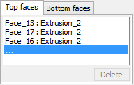
You can activate selection of top or bottom faces by clicking an empty line on the respective tabs of the Top and Bottom Faces section in the parameters window. Selection of faces, just like edges, is done in the 3D window. The selected faces will be added to the list of faces in the parameters window. To remove a face from the list, select it in the list, and then press the Delete button or <Del> key.
To cancel selection of all faces, use the option:
|
<Z> |
Cancel selection of all faces |
Defining taper angles
The command allows defining taper angles for the top and bottom faces of the source body. The angles can be defined by specifying values in the Parameters window.
To modify taper angle values, you can also use manipulators. Once the edges are defined, with respect to which the body taper will be constructed, the manipulators appear in the 3D window for modifying the angles. Those manipulators work the same way as the manipulators defining taper angles in the command Face Taper.
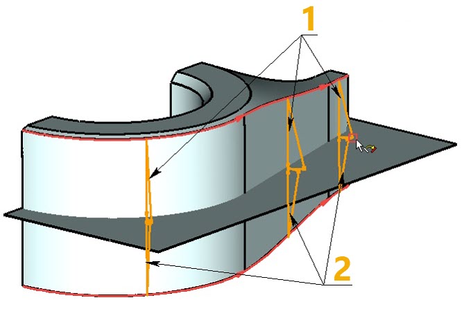
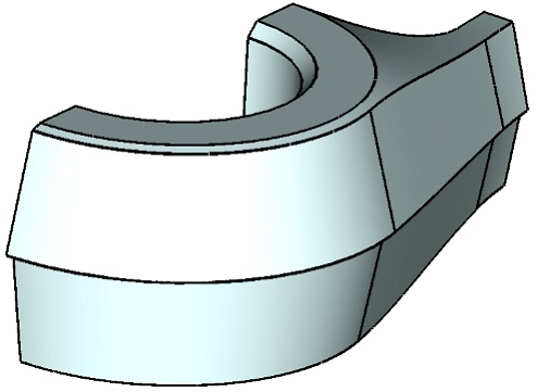
1 - Manipulators for defining top angle
2 - Manipulators for bottom top angle
At this stage, the option becomes available in the automenu:
|
<Ctrl>+<Enter> |
Finish input |
In the operation parameters dialog, called by the ![]() option, you can set common parameters of 3D elements.
option, you can set common parameters of 3D elements.