Additional Parameters of Body Taper |
  
|
Corner Connection
As a result of performing a two-sided taper, along the line separating the tapered faces of the body, a gap-step can be created due to non-uniform displacement of the “top” and “bottom” faces. It is possible to avoid creation of this step by using the mode of corner connection.
When creating an corner connection, the system automatically adjusts the displacements of the “top” and “bottom” tapered faces in such a way that they have a common edge (on the parting body). Correction of displacements is always carried out by adding material.
An corner connection can be created only upon constructing a two-sided taper with the parting surface body.
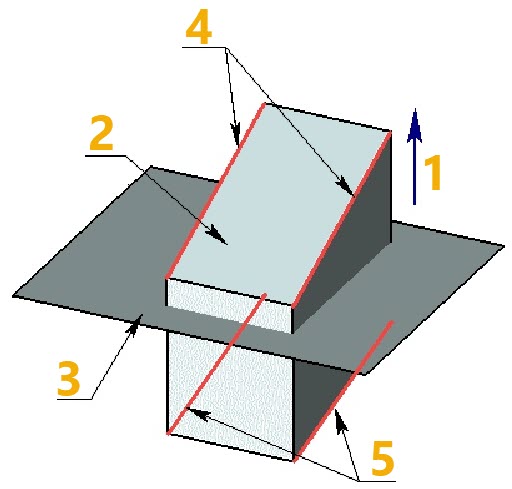
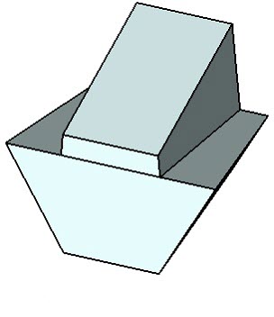
Body taper without mitering
1 - Taper direction
2 - Source body
3 - Parting surface body
4 - Top set of edges
5 - Bottom set of edges
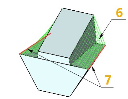
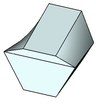
Body taper without mitering
6 - Added material
7 - Common edges of tapered faces
Creating the corner connection can be performed by one of the following methods:
•From edge – the material is added from the edge determining the given face. The boundaries of the corrected face will include the source edge specified for this face (or a part of the edge);
•Tangent to face – the material is added in such a way that the corrected surface becomes tangent to the adjacent faces (where it is possible). Simultaneously, the original edges may be deleted and replaced with the new edges created on the basis of the line of intersection of the corrected face and adjacent face;
•Combination of first two aforementioned methods – depending on the geometry of the resulting body, the system itself selects the method of creating the corner connection for each tapered face needing the correction. Priority is given to the method From edge. If, for some face, this method cannot be used, another method Tangent to face is employed.

1 - Taper without corner connection
2 - Corner connection From edge
3 - Corner connection Tangent to face
On the figure below, an example of creating an corner connection with the use of combination of two methods is shown. The “top” set of taper edges is non-closed, and it is impossible to employ the method From edge for the lateral cylindrical face. Thus, for creating a corner connection on the lateral faces of the tapered body, the method Tangent to face was used. On the end faces, the correction is carried out by the method From edge.
|
||
Body taper with corner connection obtained by combination of two methods |
|
Body taper without |
1 - Top set of edges 2 - Bottom set of edges 3 - Corner connection From edge 4 - Corner connection Tangent to face |
||
By default, in the mode of corner connection, the system adjusts the displacements of all tapered faces. If necessary, it is possible to suppress the displacement correction for any of the tapered faces.
|
|
Taper with corner connection |
Taper with corner connection |
1 - Source body 2 - Parting body 3 - Faces excluded from corner connection |
|
Taper creation method
The following methods of creating the body taper exist in the command:
•Standard – allows constructing the taper surface exactly matching the form of the source surface and a specified taper angle.
•By curve, By surface – matches the form of the source tapered faces in a less stringent manner, which allows constructing the taper in cases when the standard taper construction method does not work.
These algorithms are described in more detail in chapter Face Taper.
By default, the standard taper creation method is used in the operation. If necessary, it is possible to apply another method of tapering to the entire tapered body as well as to each tapered face individually.
Concave Edge Correction
In some cases while creating the taper with the corner connection, concave angles are created on the body, which can interfere with successful creation of taper operation.
|
|
|
Source and parting bodies |
Taper without corner connection |
Taper with corner connection causing concave angles |
To avoid such a situation various methods of processing the concave angles exist in the operation:
•No correction – created concave angles remain unchanged;
•Cylindrical surface – concave angles are “covered” with a surface of cylindrical type. Simultaneously, in the plane of a parting body the projection of the concave angle is replaced with the circular arc of specified radius.
•Mixed surface – the concave angles are “covered” with the surface of mixed type. In the plane of a parting body, the projection of an angle is replaced with a circular arc of a given radius and lines tangent to the surface of the tapered body.
|
|
|
|
|
|
Correction of concave angles |
Correction of concave angles |
|
1 - Concave angle 2 - Embedded surface |
||
Processing Connections of Tapered Faces
When creating a taper, the command provides options for selecting a method of processing connections between tapered faces. Two processing methods are available:
•Extend surfaces – in this case, the adjacent tapered faces will be extended to achieve an intersection.
•Create plane – in this method, a flat face will be created between two adjacent tapered faces.
|
||
Closing gap by flat faces |
Closing gap by extending |
|
Edge Replacement
In some cases, keeping the shape of edges defined as fixed leads to creation of redundant faces on the tapered body. To improve results of the operation, the user can allow replacement of certain “fixed” edges. Use of edge replacement guards in some cases from creation of extra tapered faces. The replacement edges are created in such away as to make a single slanted face.
|
|
Body taper without edge replacement |
Body taper with edge replacement |
1 - Edges to be replaced 2 - New edges |
|
Taper with Undercut
In some cases, creation of a taper requires not the addition but the removal of the material of a tapered body. In this situation, it is necessary to use the option of creating an undercut. Otherwise, creation of a taper will be impossible.
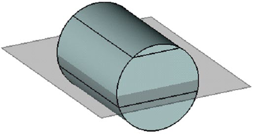
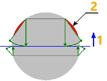
1 - Taper direction
2 - Material to be removed for creating taper