Main Concepts of Bridge |
  
|
Bridge Chains
The transition surface obtained as a result of the operation is determined by the initial chains geometry. A chain is a surface or a solid body face with an edge selected to be the boundary with the transition surface. One chain can be composed of several successively joined surfaces which can be added or deleted while setting the operation. It is obligatory that the set of surfaces in one chain belong to one and the same object or body.
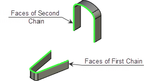
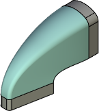
Every chain has start and end points. The transition surface alignment is determined by matching the end points between the chains. If necessary you can change the order of matching the points so that the transition surface alignment is changed too.
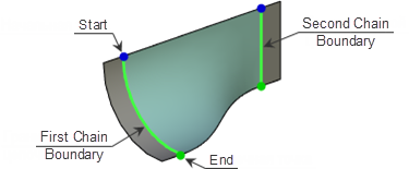
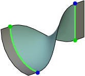
The system enables users to control the transition surface boundaries moving end points along the initial chain edges. Shift values can be set as a percentage from the boundary edge length, in units of measurement or be determined by the geometric point at the boundary. If necessary, end points shift values can be synchronized.
Shift value cannot exceed chain edge length.
|
|
|
Shift is not set |
Different values of initial shift |
Initial shift values are synchronized |
Besides shifting it is also possible to set transition surface displacement along the normal to boundary edges towards initial chains.
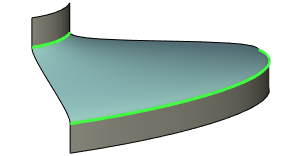
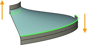
Initial surfaces can be closed. When working with closed chains it is possible to open the contour and define the circumvention direction.
|
|
|
Closed |
Open – Forward direction |
Open – Reverse direction |
Boundary Conditions
The system enables users to control joining parameters at the border line between the set of initial surfaces and the transition one, and defines continuity condition – G0, G1 and G2. It enables users to obtain a more precise surface including the one with smooth transitions.
Continuity G0 means that the boundaries of the initial limiting surfaces set and that of the transition one coincide in space.
Continuity G1 means that not only do the boundaries of the initial limiting surfaces set and that of the transition one coincide in space, but also their directions (tangent lines).
Continuity G2 means that besides mentioned above, radii of curvature at surfaces boundary coincide too.
|
|
|
Continuity G0 |
Continuity G1 |
Continuity G2 |
Tangent Magnitude value can be set for G1 and G2 continuity conditions – it is a coefficient that scales the derivative value in the given direction.
|
|
Tangent Magnitude 1,0 |
Tangent Magnitude 2,0 |
Flow Direction
Transition surface is formed by generating lines which join together the end points of both chains. To obtain a more precise surface it is allowed to determine the direction of these lines relative to limiting surfaces.
|
|
|
Auto |
Perpendicular |
Isoparametric |
There are three variants available:
•Auto. In this case the generating lines direction is determined by the system automatically so that an optimum result is achieved.
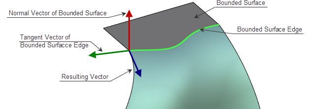
•Perpendicular. In this case the generating line vector is perpendicular to the vector of the normal to the limiting surface and to the tangent to its edge one.
•Isoparametric. In this case the generating line vector is the extension of the limiting surface directrix vector.
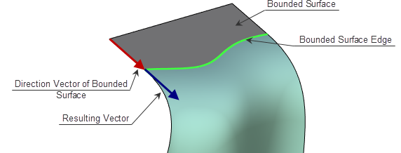
In addition to direction it is allowed to specify the tangent line modulus at the end points for the generating lines
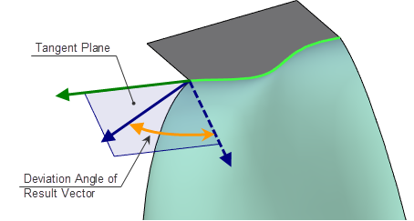
In case of perpendicular and isoparametric joining in addition to tangent line modulus it is allowed to set deviation angle vector of the generating line in the tangent plane from the initial position determined by the joining method. The tangent plane is determined by the limiting surface edge vector and the direction vector.
By default the transition surface is built so that it forms a direct contact with the initial chain as a result. However it is allowed to change the contact direction to the opposite one if necessary.
|
|
Forward tangent |
Reverse tangent |
Additional Features
By default the result of the operation is a separate surface conjugate with initial sets of surfaces. If necessary, the system allows sewing initial surfaces with the transition one to form a single surface body.
|
|
|
Set of initial surfaces |
Result without sewing |
Result with sewing |