Main Concepts of LCS |
  
|
Steps of creating LCS
Generally, an LCS creation includes the following steps:
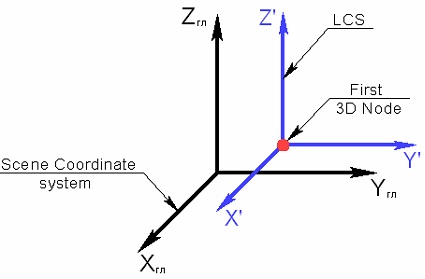
1. Selecting LCS origin. A local coordinate system is created in the selected origin point with the same axis orientation as the global coordinate system.
2. Selecting X-axis direction. X-axis of the LCS resulting from the previous step, is reoriented in the specified direction.
3. Selecting Y-axis direction. Y-axis of the LCS resulting from the previous step, is reoriented in the specified direction.
4. Selecting surface for additional reorientation. The LCS resulting from the previous step, is reoriented in such a way, that its X-axis becomes pointing at the nearest point on the specified surface.
5. Selecting tangency surface. The LCS resulting from the previous step, is reoriented to achieve tangency with the specified face/surface.
6. Selecting required LCS transformations. The LCS resulting from the previous step, is rotated about its axes.
Some steps can be skipped. The only required action is selecting the origin of the LCS.
7. Specifying additional non-geometrical characteristics of the LCS (associated elements, visibility in the assembly, etc.).
Some of the steps can be skipped. The only mandatory action is to select the origin of the LCS coordinates.
Defining the origin of the LCS
The origin of LCS is defined by a 3D point. An LCS is created in the specified 3D point with the axes orientation (X', Y', Z' on the diagram) coinciding with the orientation of the axes of the global coordinate system.
Defining X-axis direction of LCS
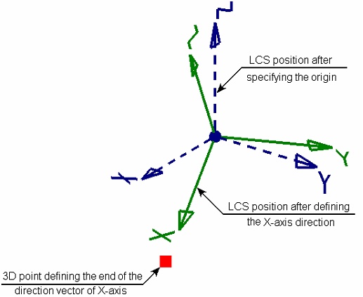
To define X-axis direction of the LCS being created, specify either the direction vector itself or its 3D end point (the first point of the vector is the 3D point defining the origin of the LCS). As a result, the coordinate system is reoriented in such a way, that the X-axis assumes the desired position.
The rotation axis is defined as follows: a plane is constructed through the two positions of the X-axis –the old (resulting from the previous step) and the new (defined at the current step). The normal to this plane, passing through the origin of an LCS, is exactly the rotation axis.
Defining Y-axis direction of LCS
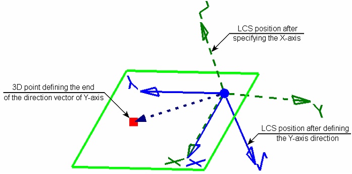
The Y-axis direction is defined, as in the case of the X-axis, either the direction vector itself, or by its 3D end point (the first point of the vector is the 3D point defining the origin of the LCS).
The step is performed only upon the condition of completing the previous one, which is the selection of the X-axis direction. You cannot define the Y-axis direction without specifying the X-axis direction.
The vector of the Y-axis direction does not define the Y-axis direction, rather, the position of the plane XY, in which this axis must be located. The plane will pass through the X-axis of the LCS and the specified vector of the Y-axis direction. As a result, the X-axis of the LCS maintains its position, and the Y-axis is located in the specified plane at the angle of 900 to the X-axis. The direction of the Z-axis is defined automatically based on the X and Y axes.
Reorienting X-axis of the LCS towards the nearest point on the selected surface
Reorienting the X-axis of the LCS towards the nearest point on surface is used in the case, when it is impossible to achieve the desired position of the LCS by selecting vector of the X-axis direction.
Upon selecting the reorientation surface, the LCS being created is reoriented in such a way, that its X-axis is directed towards the point of the selected surface nearest to the origin of the LCS.
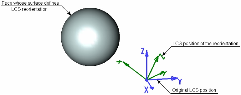
The reorientation surface can be represented by a worksurface or plane. You can also select a face, flat edge or a simple body (a body, all whose faces lie on one surface). In this case, the reorientation surface is represented by the geometrical surface underlying the selected element.
Reorienting an LCS is done similar to rotating an LCS at the time of defining the original X-axis direction.
Snapping LCS to tangency point on surface
Snapping LCS to tangency point on a face allows adjusting the position of the origin of the LCS being created.
The new position of the origin of the LCS is defined as follows: an auxiliary plane is constructed parallel to the plane YZ LCS and tangent to the selected surface. If there are several such planes, the nearest to the origin of the LCS is selected. The intersection point of the auxiliary plane and X-axis will become the new origin of the LCS.
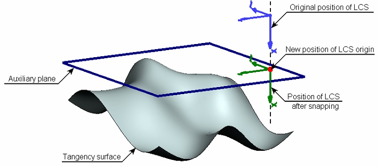
The tangency surface is defined in the same way as the reorientation surface. To do this, you can select a worksurface or plane, face, flat edge or a simple body. However, limitations are applied in this case:
• If a plane is used as the tangency surface (a workplane, and underlying plane of a flat face or flat edge), it must be perpendicular to the X-axis of the LCS;
• If the tangency surface is defined by a cylindrical face – the axis of the cylinder must be perpendicular to the X-axis of the LCS.
Modifying axes orientation of LCS
To modify axes orientation of an LCS, you need to use stepwise rotation of the LCS about any of its axes. In one pass, the LCS is reoriented by 900 about the selected axis. Additionally, a provision is made for cyclical rotation of the axes of an LCS.
If both ways of modifying axes orientation of an LCS are combined together (rotation about one axis and cyclical rotation), then the specified rotations about the specifics axes are performed first, and the cyclical rotation follows.