Visibility of LCS in Assembly |
  
|
Visibility of LCS in Assembly |
|
In addition to the geometric parameters that determine the position and orientation of the axes of the local coordinate system, a number of additional characteristics can be set for the LCS, which are necessary when using this LCS to bind 3D fragments in an assembly.
LCS visibility in the assembly
Four visibility modes can be specified in the assembly drawing for the LCS being created in the 3D fragment document (set in the External parameter, in the parameters of the LCS):
•Invisible in assembly. This mode is set on by default. The LCS created in the fragment document, will be not accessible in the assembly document. The LCS of the fragment will be visible neither in the 3D window, nor in the LCS list of the assembly model;
•Visible in assembly on one level. This LCS will be visible in the assembly model and available for snapping to it under condition that the fragment containing this LCS is a fragment of the first nesting level. The location of such coordinate system is determined by the location of the 3D fragment. This LCS can be used for attaching other 3D fragments, and also for creating any construction elements and operations of the assembly model;
•Visible in assembly on all levels. The LCS will be visible in the assembly document and accessible for snapping to it for any nesting level of the fragment in the assembly;
•Externally invisible in assembly, but available for snapping to it. This mode is used most frequently for 3D connectors operation. In this mode, by default, the LCS of the fragment is not displayed in the 3D window of the assembly model. However, upon bringing the cursor to the LCS (or to its associated elements) the LCS will be “shown” in the assembly model and it will be possible to select it for snapping. Such LCS is also displayed in the list of the local coordinate systems of the assembly (with gray color, as invisible).
The connection of the External parameter can be restored from the parameters of the LCS for the part and assembly.
Visibility of Fragment’s LCS in Assembly
The following types of LCS can be visible in the model tree of an assembly: On one level, On all levels, Connector.
Limitations:
•Connector and On all levels external LCS are invisible in the model tree until any other element is not snapped to it. You can disable the option Hide connectors in the context menu of the model tree to show the LCS.
•LCS will be hidden in the model tree if the option Hide coordinate systems in model tree is enabled in the fragment parameters.
Source LCS of 3D Fragment
Location of the 3D fragment in the assembly gets fixed by combining two coordinate systems: source one – belonging to the fragment, and target one – located in the assembly model. The LCS created in the fragment document and assembly document are usually used as the source and target coordinate systems.
However, not all LCS created in the 3D fragment document can serve as a fragment source coordinate system. The only LCS that can be selected for this purpose, are the ones that have the Use as Source CS checkbox enabled in LCS parameters.
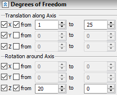
Degrees of Freedom
For the LCS which will be used as the source coordinate system upon 3D fragment attachment, it is possible to specify additional conditions in the form of allowed degrees of freedom. They define behavior of the 3D fragment with respect to the fixing LCS. When inserting a 3D fragment, the conditions with degrees of freedom are copied from the LCS parameters to the 3D fragment parameters and subsequently are taken into account when calculating the set of mates of the designed 3D assembly model.
There are 6 degrees of freedom of the fragment – 3 translations and 3 rotations with respect to the LCS axes.
For each degree of freedom of the LCS, allowable bounds on the fragment displacement can be specified.
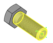
Associated Elements
For the LCS it is possible to specify associated, i.e., connected with the LCS elements (vertices, faces, edges, etc.). It will allow a user later on to perform snapping to the given LCS by indicating not the LCS itself, but the elements connected with the LCS. For example, if for the “external” LCS created in the fragment of the bolt, faces and edges of the bolt are specified as associated elements, then in the assembly when attaching a nut to this bolt, it will be sufficient to point at any face or edge of the bolt with the cursor – the LCS connected with these elements will be highlighted and selected as a result.

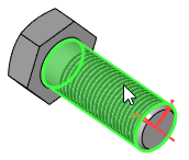
3D Fragment Insertion Rules upon Snapping to Given LCS
For LCS which is going to be used as the target LCS upon 3D fragment attachment, so-called “insertion rules” can be specified. They imply the necessity of specifying additional transformations upon insertion of the fragment with snapping to the given LCS.
For example, when a nut is snapped to the bolt LCS, it is usually necessary to specify additional translation of the nut along the bolt axis. That is why when designing a bolt model, in the insertion rules for the bolt LCS, it is possible to indicate the necessity of translation along the X-axis.