Create LCS |
  
|
Create LCS |
|
When creating an LCS, the parameters window and the command automenu are used together.
To select a geometrical element defining some parameter of the LCS (the origin, X and Y axis direction, the reorientation surface, etc.) you can simply focus in the respective input box of the parameters window. In this case, the option for defining the given parameter activates automatically in the automenu. The opposite is also true: upon activating one of the automenu options, the input focus in the command's parameters window automatically switches to the input box of the LCS parameter, corresponding to that option. For each option, you can configure filters of geometry type in the filter toolbar.
Specifying Geometric Characteristics of LCS
Note that geometry elements, defining various LCS parameters (the origin, X and Y axis direction, the reorientation surface, etc.) can be selected in arbitrary order. Those, however, will be applied in the order described earlier in this chapter.
Geometric characteristics, as well as other parameters, can be copied from another LCS using the following automenu option:
New options have been added to command's automenu:
|
<С> |
Format by Pattern |
Select an existing LCS, upon activating this option. All parameters of the selected LCS, except connector values and origin position, will be applied to the current LCS.
To select a 3D point defining the origin of the LCS, focus in the input box Origin of the parameters window. The following automenu option will become active:
|
<1> |
Select 3D Node or vertex as LCS origin |
Once the 3D point of the coordinate system origin is selected, the image of the LCS being created is displayed in the 3D window. As the rest of the characteristics are specified, the direction of the LCS axes can be modified. To define the X-axis direction, use the entry X axis direction of the parameters window and the automenu option:
|
<1> |
Select point that sets direction of X axis |
The Y-axis direction of the LCS is defined in the Y axis direction entry of the parameters window and the automenu option:
|
<3> |
Select point that sets direction of Y axis |
The surface, whose nearest point defines the reorientation of the X-axis of the LCS, is specified in the input box Rotate to Surface. The respective automenu option is:
|
<4> |
Rotate LCS to be orthogonal to Face |
To select the tangency surface, use the Move to Surface entry of the parameters window and the automenu option:
|
<5> |
Offset LCS to be tangent to Face |
The selected geometry elements (3D node, vertex, edge, etc.) are specified in the respective entries of the parameters window. To reject an element, focus in this entry and press the button Delete. Moreover, by pressing ![]() or <Esc> it is possible to successively cancel selection of all elements.
or <Esc> it is possible to successively cancel selection of all elements.
To modify axes orientation of an LCS, use the following options:
|
<A> |
Rotate LCS around X axis by 90° |
|
<O> |
Rotate LCS around Y axis by 90° |
|
<Z> |
Rotate LCS around Z axis by 90° |
The cyclical reassignment of the axes of an LCS is done by the option:
|
<Tab> |
Change LCS axes orientation |
Several LCS in row with the same orientation can be quickly created using the following option:
|
<К> |
Save given orientation |
Upon activating this option, all rotations applied to the current LCS via ![]() ,
, ![]() ,
, ![]() , and
, and ![]() options will be automatically applied to the next LCS created after the current one.
options will be automatically applied to the next LCS created after the current one.
Keep in mind, that this option doesn't affect rotations resulting from aligning axes to selected elements.
Once the desired LCS is built, confirm its creation by ![]() (in the parameters window or in the command automenu). To reject creation of the given LCS, use the automenu option:
(in the parameters window or in the command automenu). To reject creation of the given LCS, use the automenu option:
|
<F> |
Reset target LCS |
Before confirming the LCS creation with the help of ![]() in the command's parameters window, the LCS characteristics (see below) necessary for snapping 3D fragments can be specified.
in the command's parameters window, the LCS characteristics (see below) necessary for snapping 3D fragments can be specified.
Choosing LCS Visibility Mode in Assembly
When inserting the current document into an assembly as a 3D fragment, the drop down list of the parameter “External” in the group Coordinate System Parameters of the command's parameters window is used for selecting LCS visibility mode:
•Hide in Assembly. LCS will be always invisible in assembly;
•One Level. LCS will be visible in assembly on one level;
•All Levels. LCS will be visible in assembly on all levels;
•Connector. LCS will be invisible in assembly but available for snapping to it (this option is usually used for 3D connectors).
•Select Type. This option is used for 3D connectors with pre-created parameters. The LCS will be invisible in the assembly, but available for binding to it.

LCS as Source Coordinate System of 3D Fragment. Specifying Degrees of Freedom
To utilize the LCS being created as the source LCS of the fragment (upon inserting the current document into an assembly as a 3D fragment), it is necessary to ensure, that the Use as Source CS checkbox is enabled in the Coordinate System tab of the command's parameters window. When creating a new LCS, it is enabled by default.
When the Use as Source CS checkbox is enabled, it is possible to additionally indicate degrees of freedom of the 3D fragment available when given LCS is used as the source CS. It is done in the in the Degrees of Freedom tab of the LCS creation command's parameters window.
There are 6 degrees of freedom for a fragment – 3 translations and 3 rotations with respect to LCS axes. By default, all degrees of freedom are forbidden – the switched off flags found next to the strings of all degrees of freedom manifest about that.

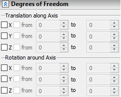
For enabling any of the degrees of freedom, it is necessary to set on the flag to the left of the corresponding string. In this case, the fragment can move along the given axis of the LCS (or rotate around the given axis of the LCS) with no restrictions.
For specifying start and/or end limits of permissible motion by allowed degrees of freedom, it is necessary to set on flags before the fields from and/or to and specify desired value in the opened entry field.
Note that for rotation around the LCS axes, two (start and end) limits of motion have to be specified at the same time. For translation along the axis, the limits can be specified independently (for example, only start, or only end limit).
Selection of Associated Elements
For specifying associated elements, the command's parameters window (group Associated Elements) and automenu can be used.
To specify associated elements with the help of the automenu, it is necessary to turn on the option:
|
<E> |
Select Associated Elements |
This option allows a user to select the associated elements for the LCS just by picking them in 3D window. The drop down list of the option contains filters for choosing the elements. The selected 3D elements are put into the list “Associated Elements”.
The option ![]() can be enabled just by putting the cursor over the string of the list containing “…”.
can be enabled just by putting the cursor over the string of the list containing “…”.
For removing selected elements, the buttons to the right of the list are used. The button ![]() allows a user to remove one element – selected in the list at the moment of pressing the button. When pressing the button
allows a user to remove one element – selected in the list at the moment of pressing the button. When pressing the button ![]() , all selected associated elements of the LCS are removed at once.
, all selected associated elements of the LCS are removed at once.

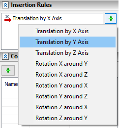
Specifying 3D Fragment Insertion Rules upon Attaching to Given LCS
Additional transformations of translation/rotation, which the system automatically prompts a user to carry out when the fragment is attached to given LCS, can be specified in the group Insertion Rules found in the command's parameters window.
To create a new rule, press the button ![]() . Upon pressing this button, a drop down menu appears in which a desired type of transformation needs to be chosen. The selected transformation is added to the list.
. Upon pressing this button, a drop down menu appears in which a desired type of transformation needs to be chosen. The selected transformation is added to the list.
|
|
For removing one of the specified transformations, choose it in the list and press the button ![]() . Pressing the button
. Pressing the button ![]() will lead to deletion of all transformations at once.
will lead to deletion of all transformations at once.