Model Check |
  
|
Calling the command:
Icon |
Ribbon |
|---|---|
|
Measure > Geometry Analysis > Model Check Analysis > Additional > Model Check Surfaces > Additional > Model Check Weld > Additional > Model Check Primitives > Additional > Model Check |
Keyboard |
Textual Menu |
<QM> |
Tools > Geometry Analysis > Model Check |
This command serves for analyzing the selected body in order to expose errors in its geometry. Errors may become an obstacle on the way of future manipulations with the model. Errors in geometry may occur, for example, due to deficiencies of importing 3D models from other systems. Sometimes, however, errors may be introduced at the time of creating a 3D model in T-FLEX, since only a local model check is automatically performed when creating a 3D operation. Meanwhile, the full check may take some time, depending on the model complexity.
Examples of some typical errors are shown below.
|
|
|
Once in the command, you can select elements to check. Those could be edges, faces or whole operations (in the latter case, all edges and faces belonging to this operation will be checked simultaneously). Use the following options for selection:
|
<E> |
Select Edge or cancel Edge selection |
|
<F> |
Add/Remove selected Face |
|
<B> |
Add/Remove all Faces of Solid |
To select all operations at once, you can use the option:
|
<A> |
Select all operations |
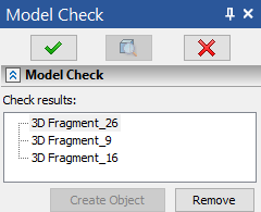
Once selected, the element is put in the list Check results.

This list displays the type of the element and whether it was already checked or not. If it was, then the results of the analysis are displayed as well.
To cancel selection of one of the elements, click it again in the 3D window. To cancel selection of all elements, use the option:
|
<R> |
Cancel selection |
To run the check on the selected elements, use the option
|
<Enter> |
Finish input |
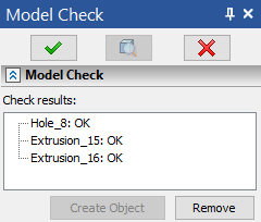
After picking this option, the system will check the selected elements and display the results in the Check results pane. If there are no errors, OK will be put next to the element.

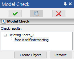
If, on the contrary, an error was found, then the list of the detected errors will be displayed next to the element name.

If you quake a particular error, then the erroneous part of the model will be highlighted red in the 3D window.
When clicking on an error, the Create Object button also becomes available, which creates a topological link (the Geometric entities folder in the model tree) to the problematic elements to simplify their removal and subsequent correction of the model.
A topological link is created after exiting the command.
You can immediately select more elements to check, without leaving the command.