Offset Body |
  
|
Calling the command:
Icon |
Ribbon |
|---|---|
|
3D Model > Advanced > Offset Body Primitives > Advanced > Offset Body |
Keyboard |
Textual menu |
<3CO> |
Operation > Offset Body |
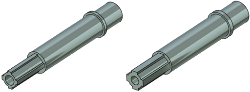
An offset body command enables users to create an equidistant not hollow body whose faces are displaced relative to the initial solid body faces along the normal at a set value. This command is helpful for creating workpieces with a machining stock or a part coating model with a given layer thickness. The offset can be performed inwards or outwards from initial body faces. You can set the same offset value and direction for all the faces or select the faces with special offset parameters.

Part and workpiece for machining
Setting the operation
Select the initial solid body. The body select mode is active automatically at calling the command.
|
<O> |
Select Solid Body |
The selected body is shown in the dialog in the corresponding field. The field can be edited: you can cancel body selection with ![]() and select another body. It is not allowed to select several bodies.
and select another body. It is not allowed to select several bodies.
You should also select the offset direction in the dialog with the help of special icons.
|
Inside |
|
Outside |
Inside – moving from the body faces along the normal inwards.
Outside – moving from the body faces along the normal outwards.
Offset field – set the offset value. If no special faces are selected, the offset value is the same for all the faces.
To select special faces, activate the automenu option:
|
<T> |
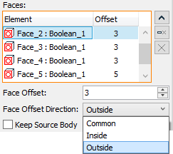
Select Face with different wall thickness |
This automenu option becomes active automatically after you select the body. The faces selected in this mode automatically get into the editable list.
You can set the offset direction and value for any element of the list. In case you choose Common variant (set by default), the offset direction is the same as for all the faces which are not on the list.
Any face can be deleted with the help of ![]() or clear all the list of faces with
or clear all the list of faces with ![]() .
.
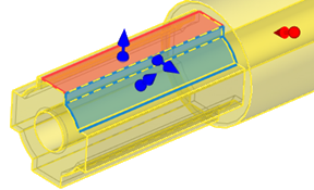
You can control the offset value and direction using manipulators in 3D window. When you select a special face, a special manipulator for it appears.


You can set the same offset parameters for several faces by selecting them in the list with the <Shift> key pressed. If manipulators are used in a 3D scene, the manipulators of the faces selected in the list will move coherently according to the movement of any of the manipulators.
To finish the command with creating the surface according to the parameters set, do the following:
|
<Ctrl+Enter> |
Finish input |
To exit the command without creating the surface, do the following:
|
<Х> |
Exit command |
Additional operation parameters
Keep Source Body. This option enables you to leave the initial body at the 3D scene along with the result. This can be helpful when it is necessary to have both part models at the same time.
The Simplify Geometry option is available in the command.
Options
Dynamic preview. The option is standard for all the 3D Design commands. It enables a simplified representation of the body being built which dynamically changes when the initial parameters change. The option is enabled by default.
Use Manipulators. The option is standard for all the 3D Design commands and is enabled by default. It enables auxiliary graphical objects – manipulators. There are two types of manipulators in this operation: common offset manipulator and special faces manipulators.