Parameters of Rotation |
  
|
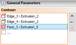
The Contour field in the General Parameters tab of the Parameters window activates in conjunction with the activation of the Select Contour option in the Automenu. Upon selecting a contour this field will contain a name of a selected element and an icon depicting a type of a selected element. Upon multiple contours selection only number of elements is shown as well as an icon depicting multiple elements. Right side of the Contour contains buttons allowing you to ![]() Clear the selection and
Clear the selection and ![]() Expand list of selected elements.
Expand list of selected elements. ![]() Clear button is also available in other fields for geometrical elements selection.
Clear button is also available in other fields for geometrical elements selection.
![]()
Clicking the ![]() Expand button changes the Contour field layout. Left side of the field will contain the list of all selected contours. The
Expand button changes the Contour field layout. Left side of the field will contain the list of all selected contours. The ![]() Expand button on the right side of the field will be replaced by the
Expand button on the right side of the field will be replaced by the ![]() Collapse button which allows you to switch to previous layout. The
Collapse button which allows you to switch to previous layout. The ![]() Delete Element from the List button also appears allowing you to delete the selected (highlighted in blue in the list) contour. Click
Delete Element from the List button also appears allowing you to delete the selected (highlighted in blue in the list) contour. Click ![]() on an element in the list if you need to select it.
on an element in the list if you need to select it.
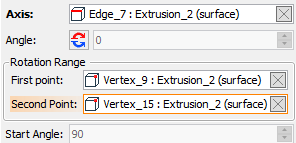
Axis.
A name of an element selected as an axis of rotation and an icon depicting a type of element are displayed in this field.
When defining an axis by two points, this field is replaced by First point and Second Point fields (not to be confused with eponymous fields in the Rotation Range group).
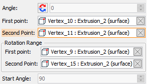
Angle.
Value of a rotation angle (360° by default). If starting and ending points of rotation are selected, this field becomes inactive and displays a value defined by difference between ending and starting points' positions.
![]() Switch rotation direction button is located near the Angle field. Clicking this button reverses direction of rotation.
Switch rotation direction button is located near the Angle field. Clicking this button reverses direction of rotation.
Start Angle.
Defines the initial point of the rotation contour's transition relative to its actual position. When starting point of rotation is selected, this field becomes inactive and displays a value defined by a starting point's position.
Rotation Range group of parameters contains two fields: First point (displays starting point of rotation) and Second point (displays ending point of rotation).
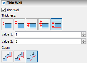
Enabling the Thin Wall checkbox activates the toolbar for selecting Thickness application direction
Following directions are available:
|
No |
|
Outside |
|
Inside |
|
Symmetric |
|
Various |
Selected option is highlighted in blue and has a black outline.
Selecting No leads to creation of a zero-thickness surface.
Selecting Outward, Inward or Symmetric activates the thickness Value 1 field and the operation yields a solid body with a thickness applied to selected direction.
Selecting Various activates thickness Value 1 and Value 2 fields, giving the ability to specify different values for outward and inward thickness. Value 1 - outward, Value 2 - inward.
The new faces in the thin-wall body are created by rotating an offset contour of the original one. The shape of the faces depends on the choice of handling the gaps when creating an offset contour. Following choices for gap handling become available on the Gaps toolbar after selecting the thickness application direction:
|
By Line |
|
By Curve |
|
Round |
Selected option is highlighted in blue and has a black outline.
Round – The free ends of the neighboring offset curves are connected by fillets.
By Line – The offset curves of the original contour are extended at their free ends by tangent straight line segments.
By Curve – The offset curves of the original contour are prolonged until intersect.
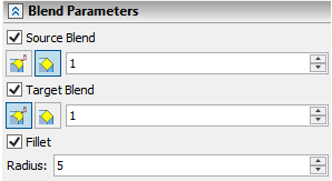
Enabling Fillet checkbox activates blending of rotation side edges. Side edges can only be blended by a round fillet. Fillet Radius can be set in the corresponding field.
You can also add blending of the top and bottom faces if the operation yields a solid body. Enabling Target Blend checkbox activates blending on the rotation ending face. Enabling Source Blend checkbox activates blending on rotation starting face. You can choose between ![]() Chamfer and
Chamfer and ![]() Round (fillet) types of target and source blend. Selected option is highlighted in blue and has a black outline. Chamfer size or Round fillet radius can be set in the field to the right side of blend type selection. Source blend and target blend are available only if rotation angle is less than 360°.
Round (fillet) types of target and source blend. Selected option is highlighted in blue and has a black outline. Chamfer size or Round fillet radius can be set in the field to the right side of blend type selection. Source blend and target blend are available only if rotation angle is less than 360°.
Source Blend and Target Blend checkboxes are not available for the Thin Wall with No thickness. Enabling Source Blend and Target Blend checkboxes for the Thin Wall with some thickness blends both inner and outer contour edges of the corresponding face. Operation can not be completed if source or target blend size exceeds half of the overall (inward plus outward) thickness of the Thin Wall.
See also:
•Common options of solid 3D modeling operations