Scale/Twist Deformation |
  
|
Calling the command:
Keyboard |
Ribbon |
|---|---|
|
3D Model > Special > Deformation > Scale/Twist Deformation |
Keyboard |
Textual Menu |
<3DRT> |
Operation > Deformation > Scale/Twist Deformation |
Scale/Twist Deformation is always specified with respect to the coordinate system of deformation (defined with the help of LCS). Twisting is performed only around the X-axis of the coordinate system of deformation, scaling is possible along all axes.
The deformation function is determined on the basis of the parameters (angle of twist and deformation scales) specified for several sections of the deformed body located along the X-axis of the coordinate system of deformation. For different sections a user can specify different scales and angles of twist along the axes of the coordinate system of deformation. For each section the scales along different axes can be also different.
The value of any parameter (except section position) can be assigned to a variable.
|
|
Deformation of the whole body |
Deformation of the part of the body |
The deformation function is calculated over the specified domain of the deformation function along the X-axis. The domain of the deformation function is defined by the start and end boundaries along the X-axis. The domain of the deformation function can include into itself the entire deformed body, only its part or extend beyond the boundaries of the body.
The computed function is applied to the part of the deformed body defined by the deformation area. By default, the deformation area is constructed as the bounding box of the deformed body (in the axes of the selected coordinate system of deformation). If necessary, the size of the deformation area can be modified by moving the faces of the deformation area bounding box. It is possible to specify location of the faces by snapping to a 3D point.
|
|
|
Domain of the deformation function |
Deformation area |
Deformation result |
Creation of Scale/Twist Deformation
After invoking this command, it is necessary to:
1.Select a body to be deformed;
2.Define the LCS of deformation (optionally);
3.Select the domain of the deformation function;
4.Select the deformation area (if necessary);
5.Define the location of the sections of deformation;
6.Specify parameters for the sections of deformation;
7.Complete the operation creation by pressing ![]() .
.
Selection of Deformed Body and LCS of Deformation
For selecting the deformed body, the following option of the automenu is used:
|
<O> |
Select Body to Deform |
This option is turned on by default upon the entry into the command. The deformed body is selected with the help of ![]() in the 3D window or in the tree of the 3D model. The selected body is highlighted.
in the 3D window or in the tree of the 3D model. The selected body is highlighted.
When you select body for the operation, the system is creating LCS for the deformations automatically. It is possible to switch between automatic creation of LCS based on global LCS and based on LCS of the selected operation using the following automenu options, which are grouped into a drop-down list:
|
<1> |
LCS by global coordinate system |
|
<2> |
LCS based on operation |
Upon switching LCS, domain of the deformation function and bounding box of the deformation area are automatically recalculated in accordance to the new axes orientation.
Instead of automatically created LCS you can select an LCS existing in the 3D scene using the option:
|
<L> |
Select Source LCS |
It is recommended to create the LCS of deformation in such a way that its X-axis is directed along the axis of the body since the twist of the body will be performed exactly around the X-axis of the coordinate system.
Cancellation of the selected LCS can be done with the help of the option:
|
<C> |
Cancel LCS selection |
Specifying Domain of Deformation Function and Deformation Area
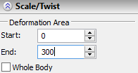
The domain of the deformation function is specified in the command's parameters window (the Deformation Area group of parameters ).
Start and End parameters define the distance from the origin of the LCS of deformation to the start and end boundaries of the domain of the deformation function. The distances are measured along the X-axis of the LCS in units of modal. The system puts the default values into these input boxes so that the domain of the deformation function spans the entire deformed body. A user can narrow or expand the deformation area by specifying other values in these input boxes.

When the Whole body checkbox is enabled, the domain of the deformation function is computed automatically in accordance with the current deformation area.
The bounding box of the deformation area initially spans the entire body. For modifying the size of the deformation area, as in the sculpt deformation, the following option of the automenu is used:
|
<D> |
Change Deformation Box |
Modifying the deformation area is performed similarly to the sculpt deformation. To exit the mode of modifying the size of the deformation area, in the automenu turn off the option ![]() .
.
Creating Sections of Deformation
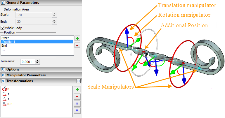
After selecting the LCS, the 3D manipulators to control location and parameters of the sections of deformation will appear on the screen. By default, only two sections are created: at the start and at the end of the deformation area. These sections cannot be removed, their location cannot be modified.

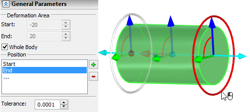
The Position list of all sections specified for the given deformation is displayed in the command's parameters window. The list in the parameters window is synchronized with the sections' manipulators in the 3D window. When selecting the manipulator of some section in the 3D window, the same section is automatically selected in the list. And vice versa: the section selected in the Position list, will automatically become active in the 3D window. Selected for editing (active) section is marked in the 3D window with color.
To add a new position click the left mouse button on the line that connects centers of two existing positions.
The buttons ![]() and
and ![]() in the Position list allow a user to create new sections of deformation and delete existing ones. The new section by default is placed after the section which is active at the moment of pressing the button
in the Position list allow a user to create new sections of deformation and delete existing ones. The new section by default is placed after the section which is active at the moment of pressing the button ![]() . The exception is the case when at the moment of pressing the button
. The exception is the case when at the moment of pressing the button ![]() , the active section is the end section – in this case the new section will be placed before the end one.
, the active section is the end section – in this case the new section will be placed before the end one.
Moving/Scaling along the X-axis is now performed with respect to the origin of the applied coordinate system. Move/scale manipulator is available for both primary ellipses.
Local coordinate system manipulator can be hidden using the appropriate checkbox in the Options tab.
Specifying Parameters of Sections
For specifying parameters of some section, first it is necessary to make it active by selecting it from the sections list in the parameters window or directly in the 3D window. After that, the section parameters can be specified in the Transformations section.
To specify the section parameters in the 3D window, the special manipulators of the active section are used. Upon bringing the cursor, the manipulator is highlighted. For modifying any parameter of the section connected with a certain manipulator, bring the cursor to the desired manipulator, press ![]() and without releasing the mouse button, move the cursor to the desired location of the manipulator.
and without releasing the mouse button, move the cursor to the desired location of the manipulator.

The manipulator of the scale also allows a user to simultaneously change the scales along the two axes (Y and Z). To do it, bring the cursor to an arbitrary point of the active section, press ![]() and without releasing the pressed mouse button move the cursor to the desired location.
and without releasing the pressed mouse button move the cursor to the desired location.