Shell |
  
|
Calling the command:
Icon |
Ribbon |
|---|---|
|
3D Model > Advanced > Shell Primitives > Advanced > Shell |
Keyboard |
Textual menu |
<3SH> |
Operation > Shell |
Shell operation enables users to create shells on the basis of solid bodies. A shell is a hollow thin-sided solid body with the sides of a certain thickness. When creating shells some faces of the initial solid body can be deleted.
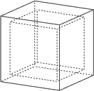

The principle of the Shell operation is as follows: an equidistant surface is built at a given distance from the initial solid body for every face. The distance can be set along the normal (outwards), contrary to the normal (inwards) or both ways. The displacement value and direction are set for all the faces at once, at the same time you can set special displacement parameters for each face. The volume within the initial surfaces of the solid body and the equidistant ones makes the shell.
Shell Creation
To create a shell, do the following set of steps:
•Select the face or all the solid body to be deleted;
•Set the displacement value and direction;
•Select the faces with special conditions of setting wall thickness and direction (optional);
•Set additional parameters (optional);
•Finish creating the operation.
Selection of a Face or a Body to Remove
To create a solid shell with one or multiple face removal, use the option:
|
<R> |
Select Face to be removed |
This option activates by default upon calling the command. It allows selecting a face or a set of faces to be removed when creating the shell. The parent body of the first selected face to be removed is also selected. The body is highlighted in this case and selected face is highlighted with color.
The faces selected for removal are added to the list in the provided pane in the parameters window on the tab Removed.
Placing cursor in the list pane in the parameters window activates the option for selecting faces to remove.
The thickness of other walls of the shell being created is defined in the input box Thickness of the parameters window. The default value is 0.06.
This means the walls of the faces left in the body will be 0.06 mm thick (the measurement units depend on the document settings).
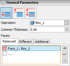
Enlargement of the shell wall may be performed inside, symmetric and outside according to the initial body. The corresponding direction selection is performed by clicking the corresponding button in the parameters window.


The wall thickness may have positive or negative value. If you specify negative value, a shell will be performed in the opposite direction.
You can also set the value and direction using manipulator in 3D window.
To create a shell without removing any faces, upon entering the command switch to the automenu option:
|
<O> |
Select Solid |
This option allows selecting a solid body to create a hollow body with the specified wall thickness.
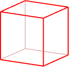
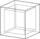
Selection of Faces with Individually Defined Wall Thickness
In case it is necessary to set individual wall thickness for one or several faces, activate Different tab. The selected faces get into a special list. The displacement value and direction for the special faces can be set either using manipulators in 3D window, or in the parameters window. The parameters can be set for several special faces at once at a multiple choice.
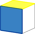
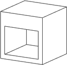
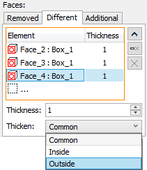
You can switch to selecting special faces with the help of the automenu option:
|
<T> |
Select Face with different wall thickness |
The faces selected in this way get to the Different tab.
Including and Excluding Additional Faces
The created shell can be altered by adding new elements to it.

Add a new element to the outer side of the shell with the help of Boolean operation. Now transform the added element into the shell.

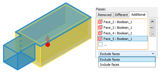
To do it, call the Shell command and select the face to be deleted: the upper face of the element. Then specify the faces to be added to the shell: activate the Additional tab and select the faces to be added from the 3D scene, they are three side faces of the element and the bottom face. Specify that the additional faces are to be added in the drop-down list: Include faces. You can also set displacement for the added faces in the parameters window, in the Thickness parameter field.
If only a part of the initial solid body is to be transformed into a shell, not the whole body, eliminate the faces without displacement, within which the solid body remains without cavity.
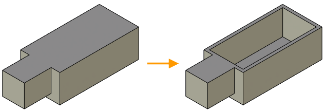
To specify such faces, select them in Additional tab and select Exclude faces. In the given example these are once again three side faces and the bottom face of the element, but here we specify that the element should not be included in the shell.
Editing is available for all the lists of the geometric objects selected: geometric objects can be deleted selectively ![]() or all the list can be deleted at once
or all the list can be deleted at once ![]() .
. ![]() icon enables users to reduce the list which optimizes the window size.
icon enables users to reduce the list which optimizes the window size.
You can finish the command with body creation according to the parameters specified in the following way:
|
<Ctrl+Enter> |
Finish input |
To exit the command without creating the body:
|
<X> |
Exit command |
Additional Operation Parameters
You can set additional operation parameters in the parameters window using the corresponding options.
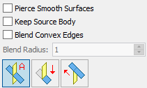
Pierce Smooth Surface. The option allows to create a shell in the cases, when the removed face is tangent to the non-planar faces. For example, it can be a rounding (radius chamfer).
Keep Source Body. The option allows keeping source body and the resulting body in the scene. It may be useful when you need to preserve two models.
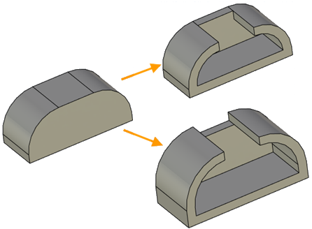
Blend Convex Edges. The option enables users to smooth convex edges obtained after adjacent faces displacement when the displacement value is the same (displacement value defines the resulting shell wall thickness). There is a limit for the option: smoothing is only performed at the radius equal to the wall thickness.
|
|
Blending of convex edges when the faces are shifted inward |
Blending of convex edges when the faces are shifted outward |
Processing the faces intersecting when extending. If the faces intersect when extending, there are three ways to process this case. User can switch between corresponding icons to select an appropriate variant for intersecting faces processing.
|
Auto |
|
Extend Moved |
|
Extend Fixed |
An extended face is a face which is moved from the initial one called fixed.

1 – extended faces; 2 – fixed faces.
Auto. The system offers a processing variant without faces overlapping if possible. Otherwise it offers any other possible variant.
Extend Moved. The faces moved overlap the fixed ones along all the face length.
Extend Fixed. The faces fixed overlap the moved ones along all the face length.
|
|
|
Auto - movable and fixed faces do not overlap |
Extend moved – moved faces overlap fixed |
Extend fixed – fixed faces overlap moved |
The Simplify Geometry option is available in the command.
Dynamic Preview
In the process of setting/editing shell parameters, the future result of the current operation is dynamically displayed in the 3D window. To increase performance, you can disable the dynamic preview by disabling the Dynamic Preview checkbox in the Options section of the command parameters window.
Manipulators Usage
Manipulators are special graphics elements, which are convenient to use to specify main numerical parameters of a shell during dynamic preview. Manipulators appear after elements selection.
There are two Manipulators types for the operation:
•Manipulator for specifying general shell thickness appears upon a body or removed face selection on the largest (not selected) face of the model;
•Manipulators for specifying thickness of different faces.
Manipulators may specify face offset both inward and outward. They are synchronized with the parameters of the direction of the faces offset.
Using manipulators while working with a large number of objects on a computer of low performance may cause a significant system slowdown. In this case, you can disable manipulators using the Use Manipulators option in the Options section of the parameters window.
Troubleshooting
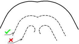
When creating Shell operation, the system may fail to calculate the result in some cases. A reason for a failure could be particulars of the source body geometry. Let's review most typical situations:
1.Degenerate faces. When creating an offset, some faces may disappear. The system may handle some of the cases. However, if there are too many such faces, or several adjacent faces disappear, the system outputs an error.
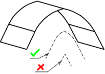
2.Offset faces do not intersect. Upon creating offset faces, the system constructs intersection lines between adjacent faces for generating the resulting body. In some cases, two adjacent offset faces may not intersect.
Topics in this section: