“2D” Tab |
  
|
“2D” Tab |
|

Node construction is transparent. Setting this parameter allows calling the node creation command from within any other command. To do so, type “N”. This will not abort the current command.
Dimension edit is transparent. This option toggles on/off the transparent mode of the command Parameters > Dimensions. The latter command allows selecting dimensions on the drawing and editing their nominal values. The construction entities that are driven by the dimension are being identified and relocated (if possible) according to the new value.
"Transparent" Element Editing. When this parameter is turned on, upon selection of 2D elements in the command waiting mode with the help of ![]() , the command of editing a selected element is automatically started. If this parameter is turned off, nothing is happening after choosing a 2D element, the system just waits for the user's commands. This parameter is turned on by default.
, the command of editing a selected element is automatically started. If this parameter is turned off, nothing is happening after choosing a 2D element, the system just waits for the user's commands. This parameter is turned on by default.
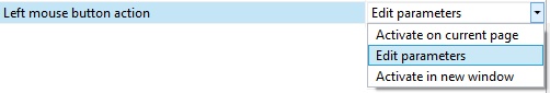
Left mouse button action. This parameter defines the action performed for drawing views on the left mouse button push while in commands. The action is selected from the pull-down list.
At your choice, pressing ![]() in different modes will either bring up a context menu or cancel the current command. For example, if the entry “Menu in command…” is selected, then the context menu on pressing the right button will be duplicating the automenu while in a command.
in different modes will either bring up a context menu or cancel the current command. For example, if the entry “Menu in command…” is selected, then the context menu on pressing the right button will be duplicating the automenu while in a command.
Node join distance. Sets the radius in pixels for locating nodes on the screen. The join distance radius is used when creating new nodes in the “free drawing” mode. If the cursor is within the join distance of some node then this node will be selected instead of creating a new node.
Node size. Sets the size in pixels of a node on the screen.
Grid point size. Sets the size of grid points on the page in pixels. Grid on the page can be customized by Edit>Grid command.
Position marker size. Specifies the size of position marker. The position marker specifies position of the dimension and value on it upon editing.
“Paper size list” Tab
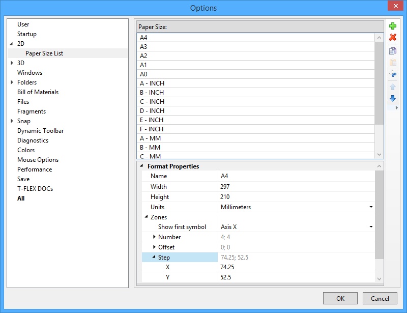
Paper Sizes. In the section you can edit the list of drawing paper sizes. This list can be edited in the drawing customization functionality (the Document Parameters dialog box, Paper tab under the Customize > Status command).
In the section you can set Name, Width and Height of a general or custom format. It also defines the measurement Units of the T-FLEX CAD system.
Besides, one can set the parameters for dividing the drawing into Zones:
Step. Defines the X and Y dimensions of one zone.
Offset. Defines the X and Y offsets of the area being divided into zones with respect to the point (0,0).
First char, X and Y. Define the characters to begin with when itemizing the zone columns and rows respectively.
Number, X and Y. The number of zone columns and rows respectively.
Direction. Defines the itemization direction for zones: left to right or right to left, top down or bottom up.
First displayed symbol. Defines, which of the zone-defining symbols (in the X or Y axis), will stand first in its notation.