“3D” Tab |
  
|
“3D” Tab |
|
This tab is specific to the three-dimensional version of the system. It defines the settings used while working with a 3D model.
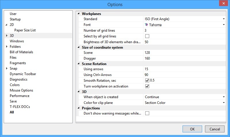
The Workplanes group of settings define various parameters of workplanes:
Standard. Defines the situation of the three default workplanes per the selected standard as follows: ANSI – frontal elevation view, bottom-up plan view, right-hand side view; ISO - frontal elevation view, top-down plan view, left-hand side view.
Font. The selected font is used for displaying the name of the workplane or workplane's type (depending on settings) in a 3D window.
Number of grid lines. This parameter defines the number of intermediate lines in the image of a workplane in the 3D view representation.
Selection of workplanes in the 3D view by default is restricted to picking at the outer lines (the border) of the workplane. If necessary, the selection can be expanded on all the lines of the workplane image, both the border and the inner grid, by setting the flag Select by all grid lines.
Brightness of 3D elements when drawing on a workplane, % specifies brightness of 3D elements, when drawing on a face or surface.
The following group of parameters allow setting the Size of coordinate system image on the 3D scene.
Dragger. Defines the size of coordinate system-like draggers used in various 3D commands.
Scene. Defines the size of the coordinate system image displayed in the lower-left corner of the 3D window.
The Scene rotation group defines the modes of spinning the 3D scene by certain increments, as follows:
Using Arrows. Defines the angle in degrees of rotating the 3D scene per a keystroke when using the two pairs of arrow keys, plus the third pair <Page Up> and <Page Down>.
Using Ctrl+Arrows. Defines a second spin-with-key mode for rotating the 3D scene by a different angle. This is similar to the “Using Arrows” parameter, except is used in combination with the <Ctrl> key.
Smooth rotation. This flag sets the smooth 3D scene rotation mode during reorientation to a standard view. The input box on the right-hand side defines the reorientation duration in seconds.
Note that setting the mode of rotating the 3D scene with respect to the global axes (the command 3RS: Rotate About Global/Local axis) makes the 3D scene spin with respect to the axes of the world coordinate system. Otherwise, the 3D scene will spin with respect to the axes of the screen coordinates.
Turn Workplane on Activation. If this flag is set, the 3D scene will be reoriented on calling the Activate Workplane command so that the active workplane becomes parallel to the screen.
3D group
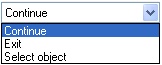
When object is Created. This attribute defines the system behavior upon creating a 3D element as follows:
Continue. The system remains within the current 3D command after creating any element. Exit. The current command automatically completes upon creating any element. |
|
Select object. The command automatically completes upon creating any element. If the created 3D element is a construction one, it is placed on the clipboard (gets selected). This mode may be convenient when the user creates an element and instantly proceeds working with it. The following is an example of such common sequence of actions: create a workplane – activate it – use it for creating an extrusion profile.
Color for clip plane. You can select Section color, Body color or Body material from the drop-down list. It will be used for clip plane displaying.
Projections group:
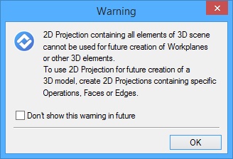
Don’t show warning messages while creating projections. If this flag is set, the warning message will not be displayed while creation of 2D projection on the plane created on the base of all elements of 3D scene.