This documentation presents a review of new functionalities, capabilities and improvements of T-FLEX CAD software solutions version 10. This information is primarily intended for experienced users who have mastered the main system tools. For a detailed acquaintance with the system functionalities, refer to the respective sections of Help or the User Manual.
New Dynamic Express Analysis Subsystem
The new dynamic analysis module is now integrated with T-FLEX CAD version 10. A free dynamic express analysis module is built in T-FLEX CAD 3D. The module uses proprietary algorithms developed by Top Systems Corp. engineers and serves to investigate behavior of various spatial mechanical systems. A mechanism's model is defined as a system of solid bodies, joints and loads. The data for the analysis is automatically accessed directly from the geometrical model created in the T-FLEX CAD system. Familiar T-FLEX CAD tools are used for modeling. Mates and degrees of freedom are used to define dependencies between three-dimensional solids. The loads on solid bodies are defined as the initial linear and angular velocities, forces, moments, springs, gravity, etc. To read the results, special sampling elements are used. Limitations are imposed within the free module on processing the calculation results. In the commercial module, the calculation results are displayed as graphs, dynamic vector arrows and as an array of numbers (graph points). Numerous values are available for the analysis: coordinates, velocities, accelerations, reaction forces in joints, forces in springs, etc. The user can observe the model behavior from any viewpoint immediately during the actual calculation. One can create animation clips from the obtained results of a dynamic calculation.
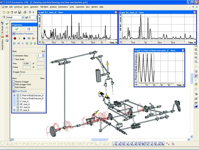
The module interface is similar to that of certain world-renowned counterparts, while the internal design is significantly different, exceeding the counterparts in the robustness and functionality, while in some cases showing a somewhat relaxed accuracy. A unique functionality is realized, which is the instruments for modeling contacts between arbitrary solid bodies capable of processing a simultaneous contact impact of hundreds and thousands of arbitrary-shape solids.
Improvements to the Strength Express Analysis Subsystem
When running a finite element analysis, it is now possible to select Bodies as source elements. This allows defining the boundary conditions for the study, then, if necessary, work more on the model, and only after that run the calculations. The boundary conditions will be automatically transferred on the Body's faces and edges that were modified at the reworking stage.
In the following example, a distributed load (pressure) is applied to the top faces of the beam, after which additional ribs are introduced in the model. The system has automatically accounted for the introduced changes.
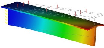
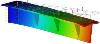
The finite element analysis system now permits the use of orthotropic materials, which are those having different properties in the different directions.
New Commands and Tools
Means for Creating and Depicting Welds
A command complex is introduced for welded part design. When creating a drawing or a 3D model, it is possible to create all kinds of welds provisioned by the standards, and, if necessary, nonstandard ones. To work with the list of welds, there is a set of various utility tools. A weld with an appropriate notation can be created in a 3D model or in a drawing. In the case of a 3D model, the location of a weld will be marked by a special "cosmetic" body with a specific texture. In a drawing, welds can be created using the data from a 3D model, if a projection thereof is being created. The user can build tables from a list of welds. It is possible to export a list of welds into an external file, and, vice versa, get the data for the table from an external source.
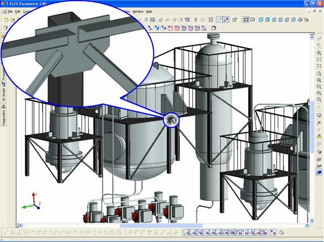
All welding commands are collected in one group of the text menu "Tools|Weldmentа"
A new "Welds" tool window is introduced in the system. It serves to manage a welding project within the current document. In this window, various commands for working with welds can be called via the context menu.
Besides a special window, a new toolbar is introduced in the system with the buttons to call welding commands.

New "2D Weld" Command
This new command serves to create a "Weld" element based on drawing elements – graphic lines, 2D paths or hatches. The "Weld" element is created based on weld types registered in the project. When creating a weld, its length can be automatically calculated based on the geometry of the used drawing elements.
New "3D Weld" Command
This new command serves to create a "Weld" element in a 3D model. When creating a 3D Weld, a cosmetic 3D operation is created that mimics a weld in the 3D model. The body of a weld cannot be used in other operations.
New "Weld Annotation" Command
This new command serves to create a special dedicated "annotation" in a drawing in order to have a representation of a weld in a draft. A created weld annotation maintains a relation with its weld.
New "Weld Table" Command
This new command generates a listing of welds existing in the document. The listing layout can be accessed from the set of ready-made templates or created by the user manually.
●Large Assembly Management Tools
To optimize working with assembly models, the system provides specialized large assembly management tools. Those allow working only with the subassemblies of concern, save the overall used memory and facilitate spinning the 3D scene when it is densely populated with objects. A "large assembly" is a model with the respective parameter activated – the "Large Assembly Mode". It can be turned on automatically when exceeding the minimum amount of geometrical data defined in the system settings. First of all, the large assembly mode provisions for freeing memory by automatically unloading the detailed information about the assembly objects. Such bodies are displayed seemingly normal, however their edges, vertices, faces, etc. cannot be selected. Such parts are highlighted in a special color when selected and are marked in the model tree with a special icon ("feather"). The omitted data is loaded automatically as needed. Such a need arises when editing parts, when performing various modifications and geometry analysis, as well as when creating projections. Besides that, a model may be stripped of cosmetic threads and small features whose size is less then the specified, which also reduces the system memory consumption. The 2D Projection creation command gained the capability of creating drawings based on a 3D model located in an external file. This helps ease working with large assemblies by separating the model handling process and the drawing creation. An associative relation is still maintained between the drawing and the model.
When in the large assembly mode, the context menu on selected parts gains special commands that serve to:
• Unload Body geometry;
• Load Body geometry;
• Block geometry unloading. When this option is active, the geometry of the concerned body will not be unloaded automatically.
●Rollback of 3D Model
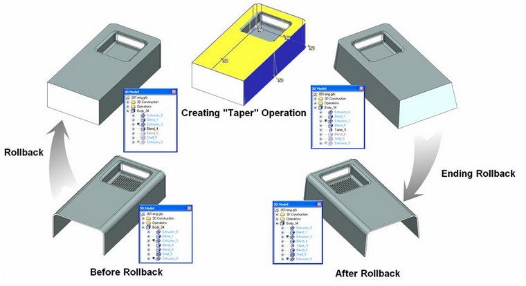
The system gained a capability to roll back the three-dimensional model to the level of a specified operation. This functionality is helpful in the cases when it is necessary to work more on the model somewhere in the middle of the model tree, that is, revert it to an earlier creation stage. Elements and operations that follow after the rollback point in the model's history become hidden in this mode and are inaccessible to work on. In this state, those are marked by semitransparent icons. All newly created elements and operations in the rollback mode are automatically inserted in the model's history. At each such instant, the system automatically rebuilds the involved dependencies as necessary to be able to re-create the following operations. If for some reason the introduced changes result in errors in the model, then the system will offer restoring the model state before the rollback. This protects the user from introducing invalid modifications to the model.
●Graph Handling Tools
A new object type is introduced in the system - the "Graph". A graph is a function based on a set of points in its own two-dimensional coordinate system, connected by a polyline or by a smooth curve. A graph serves to define relations of various nature and to store and display the results of dynamic analysis. Graphs are created and stored in the document together with the drawing and the 3D model.
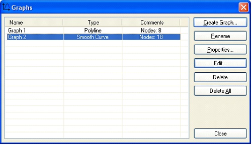
The new "Graphs" manager (accessible via the menu "Parameters|Graphs…") serves to create, edit and delete document graphs.
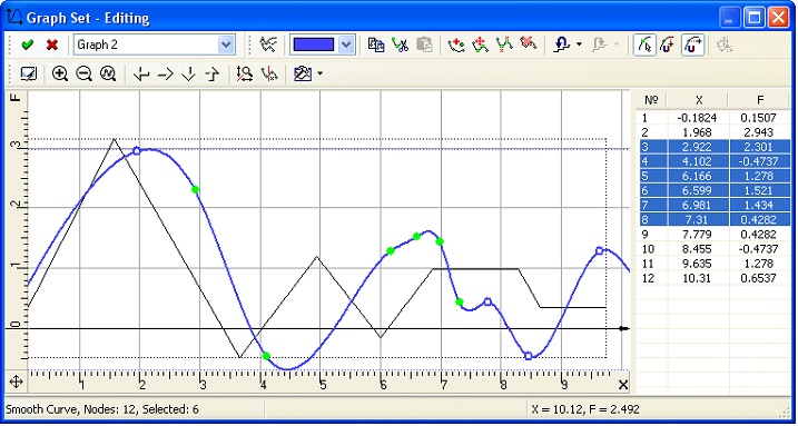
To edit graphs, there is the "Graph editor". In it you can edit one or several graphs simultaneously. Point coordinates are displayed in the right part of the editor window. The editor supports multiple point selection, as well as clipboard handling (copy/paste), undo/redo actions, axial scale control, points dragging etc.
Graphs can be used in the variable editor to get the values they define. To do this, the new "graph" function is introduced. The expression graph("Graph 2",0.5) returns the Y value, corresponding to the value 0.5 of the X.
The graph editor can be used as a convenient auxiliary instrument to define table relations and some 3D operations. For example, you can call the graph editor in the variable-radius edge blend operation properties dialog in order to define the rule of the blend radius variation and graphically define the curve shape.
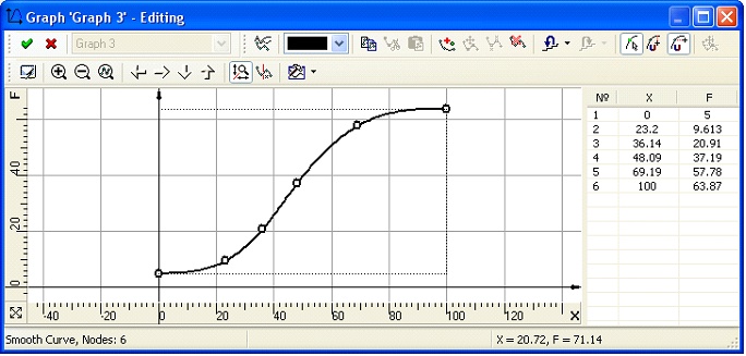
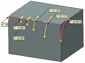
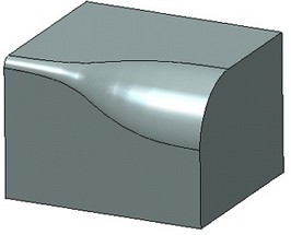
It is also possible to graphically define the rules of scaling or twisting in the "Sweep" operation, in the properties of an offset 3D profile to define the offset distance.
●Creating Annotation Elements on a 3D Model
The new version now supports the three-dimensional drawing creation functionality. The usual commands for creating a drawing annotation elements (roughnesses, leader notes, dimensions) can be used in the 3D window to create the respective elements directly on the faces of a 3D model.
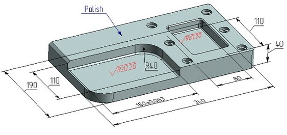
The capability of creating three-dimensional annotation elements allows instantly introducing in the 3D model not only geometrical, but also technological process and other information that can later be used when creating drawings by projections, as well as in other applications, for example, in the process design modules or when creating CNC control sequences.
For example, if a dimension between faces or a dimension on a cylindrical face (radius or diameter) uses a tolerance or additional text lines, then, when creating the dimension in the drawing you select the respective lines on a projection - this information is automatically passed on to the dimension on the 2D projection. The same happens when creating a roughness symbol on a face – if you create a roughness symbol on the respective lines of the 2D projection image, then the roughness parameters will be copied from the 3D model.

The 3D dimensions can be automatically created based on the dimensions in the workplane, in which the profile is drawn, or created directly on faces of a three-dimensional body. A new parameter is introduced for a workplane: "Show 2D Annotations on 3D View". When activating it, the drawing annotation elements created by the user on the workplane page become displayed in the 3D window. Such dimensions can be used for modifying the display parameters on the workplane page and, respectively, the 3D elements created based on it (profiles, operations etc.).
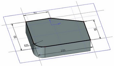
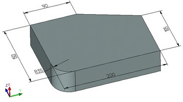
When creating three-dimensional operations, an option becomes available for automatic creation of 3D dimensions that define the main geometrical parameters of operations. Such a dimension will be directly related with the operation that produced it and is a driving one. As its nominal value is modified in the command "Parameters|Dimensions|Set Value", the respective parameter of the dimension-producing operation will change. The driving dimensions can also be created manually by the user, when the faces are selected that correspond to the operation's parameter value. For example, you can use the opposite faces of a body created by extruding, or a cylindrical face created by blending. By using such dimensions, you can control the model parameters by modifying their nominal values. You can also use the dimensions corresponding to the driving ones, that are created on 2D projections, in order to modify the values of operation parameters. The system will match such dimensions automatically.
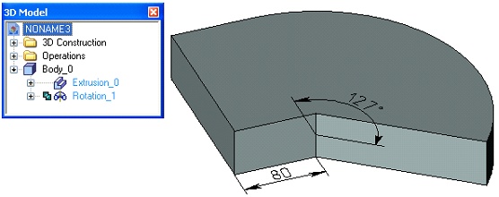
The drawing annotation elements based on the 3D model can be hidden or displayed in each particular window using the new command "View|Hide Annotations".
●Managing Model Via Dimensions

Dimension Value Modification Command. The system command has been considerably improved that serves to modify a model via dimensions. The user specifies the new dimension nominal value, and the system automatically rebuilds the 3D model or drawing based on parametric dependencies. It is also possible now to adjust the nominal value in the newly created 3D dimensions (created in the 3D model) and their respective dimensions on 2D projections. This command now works successfully on drawings and models of a much higher complexity than before.
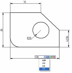
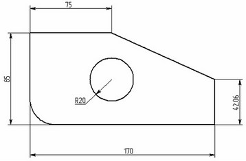
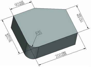
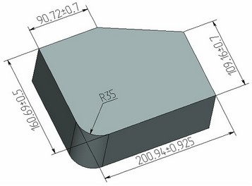
"Recalculate Dimensions to Middle of Tolerance Field" Command. A new command is introduced to recalculate model dimensions to the middle of tolerance fields. It uses the system capability of modifying the model via dimensions. This command performs a correction of nominal values for all dimensions in such a way as to make their values balanced about the median of their own tolerance range. Accordingly, the new tolerance range ("field") becomes symmetrical. This functionality is handy to use when adapting a 3D model to the toolpath calculation in the CNC module.
New "Paste Special" Command
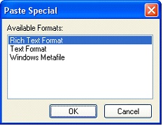
A new "Paste Special" command allows selecting a format to use when pasting from the clipboard. The command displays the list of formats that are present in the clipboard at the time of pasting. Depending on what format the user selects, the system goes into the T-FLEX CAD object pasting mode, or pasting pictures in the Windows Metafile format, or pictures in the Windows Bitmap format, plain text or formatted text.
●Raster Image Export Command
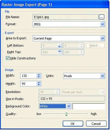
The system gained a new functionality to export raster images (command "Export"). The list of available export formats has been expanded, with the addition of the JPEG, PCX, GIF and TIFF formats. The bitmap image export command is now available in both 3D and 2D windows. The export setup dialog allows defining the output range of the image with the capability of either manual definition or the mouse input; the size of the resulting raster image in pixels, millimeters, centimeters or inches; the image resolution in pixels per inch or in pixels per centimeter; the image background color; the image compression rate for the compression-supporting formats.
Changes in commands
3D Operations
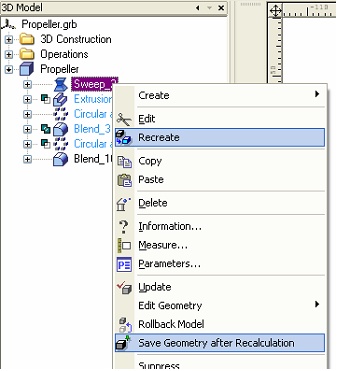
A new "Recreate" item is introduced in the context menu for all 3D operation and some 3D elements. When it is called, the system goes into the command of creating the element of the respective type with the purpose of creating this element from scratch. In this way, it is possible to change an element definition method to another one.
Operations also gained a new option "Save Geometry after Recalculation". When enabling this option, the operation will maintain its geometry even if located in the middle of the model tree. This helps speed up the editing process for operations located after a given operation in the tree, by avoiding the necessity of recalculating geometry of high-complexity 3D models. When the "Save Geometry after Recalculation" option is enabled, the operation icon in the model tree is marked with a special symbol.
Besides a manual instruction to "save geometry after recalculation", the system provides for automatic body caching. Its working principle is as follows: several geometry saves are automatically performed on the longest history branch for each body in the model. Besides that, the geometry of the second-last operation is stored, along with that of the operation located before the last edited one. All those auxiliary data exist only during a working session and are generated upon the first recalculation, without being saved to a file. Such measures help drastically reduce the time of editing complex-geometry models, albeit at the expense of an increase in the used memory. We shall note that this in no way affects working with assemblies, since fragments do not have a model tree.
●Working with the Property Window
Several more commands now can work together with the property window when defining parameters:
• "3D path" command now works with the property window in most cases, when the object being created allows numerical parameters definition;
• "Sew" operation supports managing the list of selected elements in the property window;
• "Material Application" operation supports management of the list of selected elements in the property window when defining the operation.
●"Workplane" Command
"Workplane" command gained new methods of creating workplanes:
• Workplane by two points at an angle to an arbitrary plane defined by a flat face or another workplane.
• Workplane going through a point and tangent to a cylinder or cone surface.
• Workplane going through two points and tangent to a cone, cylinder or sphere.
• Workplane in between two other planes defined by workplanes or faces. A numerical parameter controls the position of this workplane. When the parameter is equal to 0.5, then such a plane becomes the symmetry plane for the two source planes. If the source planes are parallel, then the resulting plane divides the distance between them in the specified proportion. If those are not parallel – then it is the angle that is divided proportionally.
Managing Workplanes
Workplanes can now be created based on three-dimensional geometrical objects - cylindrical, spherical and toroidal faces. After selecting a face, the workplane creation command automatically creates a new page for it, where you can create a 3D profile image. The surface orientation and geometrical parameters are automatically read from the source face. Workplanes also gained the "Offset" parameter, which defines the equidistant offset of the workplane from the source face.
The system gained a capability to activate a workplane when it is selected in the 3D window. The working principle here is the same as adopted for workplanes. When calling the command "Draw On Workplane" for the selected surface, a window opens with the given workplane page active. Upon finishing drawing on it, the appropriate 3D profiles are automatically created based on the graphic lines or hatches.
●"Extrusion" Operation
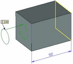
When creating the "Extrusion" operation, it is now possible to select a base element, with respect to which the extrusion length will be measured. Such an element can be a flat face or a point. If a driving dimension is automatically created with the operation, then it is also constructed from the base face. Another extruding mode is introduced, "Through All by Direction". This mode allows creating holes that are not through the entire model (as in the "Through All" mode), but only through in one direction from the profile. The hole direction can be flipped to the opposite.
"3D Fragment" Command
When inserting and editing 3D fragments, it is possible to select the source local coordinate system in the transparent mode from the drop-down list in the property window. The list contains all local coordinate systems from the fragment file intended for snapping it (those with the "Use for Fragment Fixing" flag set).
"Open Part" Command
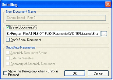
The "Open Part" command has been improved, which activates for 2D and 3D fragments via the context menu or from the editing command. Now, when performing this command, a dialog appears in which you are asked to define the name of the document being created, whether to save it immediately to a file, options to control the substitution of the assembly document settings and the external variable values or geometrical parameters. The latter are used for fragments created in the assembly context, or for adaptive fragments. The dialog display can be suppressed if desired.
●"Pipe Path" Command
Improvements are made to the command "Pipe Path". It became possible to select a 3D point or a coordinate system, with respect to which new 3D nodes will be created, that will define the 3D path geometry. Also, a new mode is introduced when working with the drawing plane, that allows to project various points of a 3D model on the drawing plane as necessary.
Local Coordinate Systems
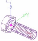
It became possible to draw coordinate system axes in different colors. The axis colors (red, green, blue) match the colors of the axes in the 3D window.
●"Material Application" Operation
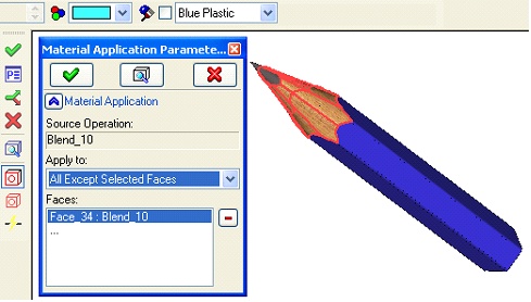
The new mode "All Except Selected Faces" is introduced in the operation "Material Application", in which the material is applied to all faces of the selected operation except for several selected ones.
"Spiral" Operation
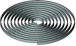
In the "Spiral" operation it is now possible to set the zero step between coils. This allows creating flat spirals and flat spring models.
"Array of Faces" Operations
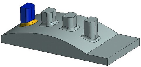
Arrays of faces by duplicating sets of faces with blending at the copied surface junction will have an automatic adjustment of the blend surface for each instance. This functionality is available only when creating an array that spans one face.
"3D Profile" Command, Face Unfolding
When creating a unfolding of a set of faces, the "3D profile" command now can unfold arbitrary ruled surfaces. Previously, this command supported only special-case surfaces – cylinders and cones.
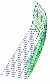
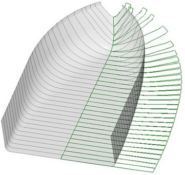
The "Keep Edges in Bend Area" option is added in a 3D profile created as unfolding of a set of surfaces, which allows displaying edges on the resulting profile in the junctions of unfolded faces.
"Model Separation Check" Сommand
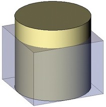
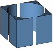
The command that analyzes separability of a diecast or injection mold now became capable of examining two additional sets of faces – "top faces" and "bottom faces". Such sorting of the analysis result is helpful to determine and select the top and bottom parts of the diecast model working zone.
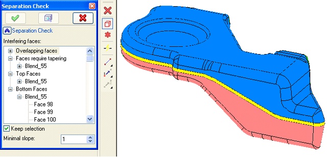
●"Fill Hole" Оperation
The "Fill Hole" command now became capable of automatically selecting all internal contours representing holes in a sheet body, all at once. This capability is handy when forming the working zone of a die cast mold.
"Loft" Operation
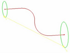
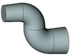
The "Loft" command gained an improved algorithm of processing the case of the "along 3D path". In most cases, the resulting surfaces are now of a higher quality.
"Blend" Operation
All blend operations ("Blend Edge", "Blend Face-Face" and "Blend 3 Faces") got an improved algorithm of processing self-intersecting surfaces, which significantly increases the robustness in complex cases.
Boolean Operation
When a Boolean operation is calculated, the degenerate cases handling is improved. The system now will attempt creating topologically correct models even in the cases of user errors.
●"Leader Note" Command
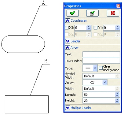
The "Leader Note" command allows creating new types of leader notes in drawings. Introduced are two new types of the leader note ending (in place of an arrow), which can be used for annotating detailed views: an oval and a rectangular area. Two dimensions are specified for such notes – width and height.
Graphic Lines Editing Command
Automatic Editing of the Defining Construction Line. The process of editing graphic lines is somewhat changed. Now, the command to edit graphic lines allows simultaneously using the editing command of the construction line on which it is drawn. This enhances the user comfort when changing the underlying geometry of the edited graphic line. To use the new capability, after selecting a graphic line the user needs to click the graphic line once more. If the underlying geometry (position or, for example, circle radius) is defined by a construction line, then the system automatically goes into the command of editing construction.
Using Relations when Editing Graphic Lines. When selecting a graphic line to edit, the system automatically displays the relation elements, that reflect parameters of the defining construction line. The user can simply click a relation mark to edit the respective model parameters.
A button for a quick change of the arrow direction is introduced in a line's parameters window. When clicking this button, the arrows at the ends of a graphic line (if any) are swapped.
Construction Line Editing Command
When editing a construction line, a mark of the respective relation appears, that reflects the geometrical dependency and the numerical parameter of the line being edited. The user can use this mark the set a numerical parameter value. To access the relation mark from the dynamic line parameter modification mode (when a line rubberbands following the cursor motion), it is necessary to turn off the dynamic model regeneration mode:
![]() <D> Dynamic model regeneration mode
<D> Dynamic model regeneration mode
Commands to Create Drawing Annotation Elements (Dimensions, Roughnesses etc.)
The annotation element creation commands have been improved. Those now employ object snaps similar to other commands, and support the mode of automatic parameterization. Such commands now allow defining parameters by the elements being created via the property window, which supports definition of all element parameters, including coordinates of the input snap points. Different-purpose properties are grouped on the opening tabs.
Projection Creation Command
The command to create 2D projections gained the capability of creating a projection based on a 3D model located in an external file. The projection can be created in any 2D document by simply selecting the file containing the 3D model, for which the projection is being created.
When creating a face projection in the mode "without hidden line removal", outline (silhouette) edges are now created. This helps more comprehensibly project individual faces with such surfaces as cylinders, cones or spheres.
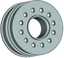
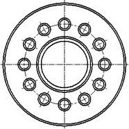
A capability is introduced for joining the center lines of holes. When creating 2D projections with automatic center line creation, the system can automatically generate axes of holes positioned on a circle, as a common circular line and radial segments.
T-FLEX CAD version 10 allows breaking the dependency of a projection on the model. In this case, all lines of the projection are turned into a nonparametric sketch with free nodes. The command to break the dependency is found in the context menu when right-clicking ![]() projection lines, hatches or a 2D projection itself.
projection lines, hatches or a 2D projection itself.
In the projection parameters dialog, a group of options to work with 3D welds is added on the "Common" tab. If the "Consider Welds" mode is enabled, then the "Fill Welds" option is available, which allows displaying welds on a 2D projection in a special way, which were created in the 3D model.
A new command is introduced in the context menu on selecting a 2D projection, that serves to automatically "project" ("map") 3D annotation elements (dimensions and roughnesses) on the selected view. When working in this command, the user needs to select the desired dimensions and roughness symbols. The annotation elements created in this way on the projection will inherit the parameters (nominal values, tolerance parameters etc.) from the respective elements of the three-dimensional drawing.
When creating and editing a projection, a new capability is introduced for an arbitrary view to quickly change the viewing direction to the opposite. To do this, use the new button with the tooltip reading "Reverse", located on the "Parameters" tab of the property window.
●"Hatch" and "2D path" Commands
Sensitive issues about inputting hatch contours and 2D paths have been addressed. A capability is introduced to use graphic lines created by nonparametric sketching when manually defining a contour.
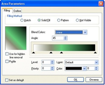
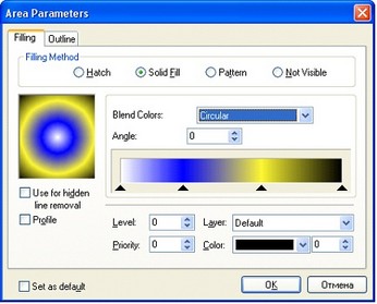
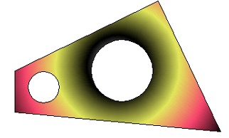
The "Hatch" command gained the capability of creating a fill with a transient color. The color gradient can be linear or circular. The color transition can involve an arbitrary number of colors. For the linear gradient, you can specify the fill rotation angle. For the circular gradient, you define the centerpoint within the hatch contour.
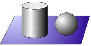
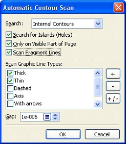
A capability is added in the automatic hatch contour searching mode to account for graphic lines of a 2D fragment. To enable such mode, set the respective flag in the automatic hatch contour search settings dialog.
Layers Management
The layers management command gained the capability to set the thickness of all graphic lines on a given layer.
General System Changes
Managing System Settings (Environment)
The system gained a capability to save the user customization of the interface and the program layout to be able to restore it later. The system settings are stored in a new "Environment"-type element. The set can be saved into a separate file or into the operating system registry. The environment set of data can store:
• Location and composition of toolbars.
• Position, visibility and settings of tool windows.
• Command-launching key combination settings.
• System color settings.
• System settings.
• Various settings in the variable editor, model and other commands.
• The composition of the loaded library configurations.
• Various other settings.
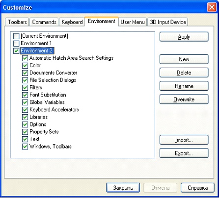
The New "Environment" Tab in the "Customize" Dialog. The "Customize|Customize…" command dialog gained the new "Environment" tab for working with environments. Here you can access the functions of creating, deleting, saving, loading environments, etc.
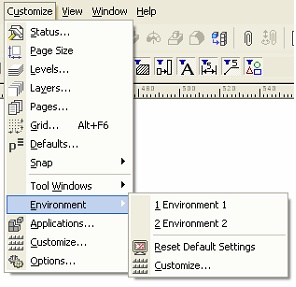
The environments existing in the system can be quickly loaded using the textual menu. The respective items are automatically added in the "Customize|Environmentа" submenu. Besides that, to load an environment, you can use the keys <Ctrl+1> - <Ctrl+0>, according to the environment number in the list of created environments.
Object Snapping Management System
The object snaps, previously available only in the sketch editor, now can be used in all 2D system commands. The snaps management toolbar is now located at the bottom of the screen and appears automatically upon the first launch of the system. Several new types of snaps are introduced:
• Graphic Line End Points
• Graphic Line Continuation
• The "Arc/Circle Center" snap now works upon approaching to the arc or circle line itself if snapping to graphic lines is disabled
• The "Arc angle 90, 180, 270 degrees" snap is singled out as a separate command
![]()
The snap manager performance has been significantly improved. How quickly snaps work now depends only on the number of visible objects in the visible portion of the page and does not depend on the total number of elements in the current drawing. Working with drawings containing hundreds of thousands elements became most comfortable ever.
When working with snaps, if several possibilities simultaneously appear at the cursor position, the system allows the user to select the desired snap. To do this, rest the cursor briefly, so that a special widget appears on screen next to the cursor with the number of possibilities; the user can select the desired snap by spinning the mouse wheel or by pressing the keyboard buttons "Up" or "Down".
It also became possible to manage snap priorities. A specific priority defines, which snap possibility the system will offer first.
●Automatic Parameterization
The unique means of creating a parametric model are subject to constant improvement in T-FLEX CAD. The system has now gained the new "Automatic parameterization" mode. It will certainly help the users who has been routinely working with various CAD systems and is accustomed to use ordinary nonparametric sketches when drawing in T-FLEX. Once the automatic parameterization mode is enabled, it is now possible to create fully parametric drawings (as per the unique powerful T-FLEX CAD parametric capabilities based on construction lines) by means of ordinary sketching.
![]()
Instead of nodes in free coordinates, T-FLEX CAD has now learned to create a parametric model using construction lines. It will automatically slip the required construction lines beneath the graphic elements being created. The types of geometrical relations (parallelism, tangency, horizontality/verticality, midpoint of a line, etc.) are automatically picked by the type of the used object snap. Also considered are the parameters of distances, lengths, angles etc., which were specified by the user when creating elements. The automatic parameterization mode works not only in the sketch editor, but also in other commands where the respective snap modes are available. To control the automatic parameterization mode on and off, the respective button is provided in the standard toolbar.
●New Means to Manage a Parametric Model. Relations
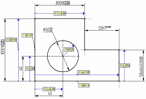
To raise the effectiveness of managing a parametric model, a new instrument is created in the system that allows displaying geometrical dependences in the model and control its parameters. Elements of a new type - relations - serve to comprehensively visualize and modify the types and parameters of geometrical dependences between construction elements – the backbone of a T-FLEX CAD parametric drawing. Relations of auxiliary objects that are displayed within the drawing field in the way of special marks. Those are not printed and are not exported.
The commands to create relations enable the user to create a relation objects of certain types, whether for all objects of a given a model, or only for some of them. It also serves to create chains of relations for specific groups of elements according to the hierarchy of their parent elements. The information about the type of the geometrical dependency and the numerical parameter of the object, on which the relation is built, is displayed within the relation mark. If a parameter is related with an expression or with a variable, then the relation mark displays both the expression and its current value.
The user can at any time modify the expression or its value by simply clicking in the relation mark field. The relation objects also appear automatically upon an attempt to modify graphic lines. If a graphic line's geometry is defined by a construction line that uses a parameter, then, when editing such graphic line, the respective relation object appears on the screen, allowing to modify that parameter in the transparent mode.
The system gained new commands to work with relations. The command to create/edit relations is located in the menu "Parameters|Relations". The "Show/Hide Relations" command, whose icon is put on the "View" toolbar, serves to control the visibility of relation objects in the current window.
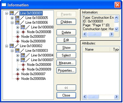
When the "Info" dialog is activated for selected or all model elements, the relation objects are displayed in a special way. An existing relation icon is placed next to the element, to which it pertains.
It is possible to define font parameters to use when displaying relation marks. For this, use the context menu command "Font" when editing the mark's value.
Measurements
New functionalities are introduced in the "Measure" command:
• It is now possible to measure the mass of operations at a 3D node created in the center of mass of those operations.
• New functionalities are added, that allow measuring new types of relations when measuring two elements:
o AxisFaceDistance - the distance between the axis of the first element and the second element;
o FaceAxisDistance - the distance between the first element and the axis of the second element;
o AxisGeomDistance - the distance between the axis of the first element and the geometry of the second element;
o GeomAxisDistance - the distance between the geometry of the first element and the axis of the second element.
Document Settings
The "Apply Scale to Projections" option is introduced on the tab of the document settings dialog ("ST: Set Document Parameters" command, [Dimensions] tab). It forces the page scale to be applied to dimensions created on projections and drawing views with scale. In this way, the referred parameter fixes the problem of matching different scales.
Changes in the Interface
Selecting Elements by the Crossing frame
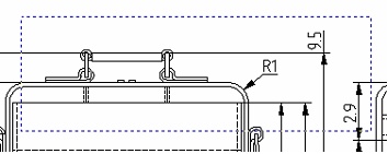
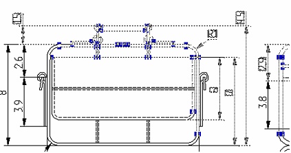
The mechanism of selecting a group of objects by a frame is improved. Now, while working outside commands, the user can use a new crossing frame. The crossing frame appears, if, when selecting objects, the cursor is moved right to left. The crossing frame means not only the objects are selected that lie fully within the selection box, but also the objects that are crossed by it. Unlike the conventional frame, which is drawn on the screen in a solid line, the crossing frame is displayed in a dashed line.
Visual Means of Creating and Editing 3D Operations
When creating and editing operations, besides the draggers defining the operation parameters, the marks with the values of those parameters may be displayed on the screen. A mark contains an icon indicating the type of the displayed parameter, and also shows the current value of the parameter.
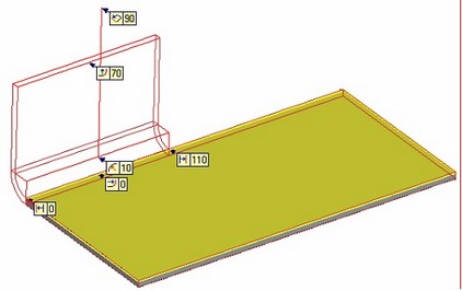
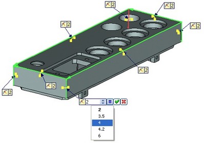
As the parameter value is modified via the property dialog or a dragger, the value on the mark changes dynamically. Upon clicking the mark, the value of the respective parameter can be edited in place, in the transparent mode. Just like in other system fields for editing values, the user can create the list of frequently used parameters and use it with the help of a special button for selecting the value from the list.
Means to Manage a 3D View
The system gained a capability to draw shades in a 3D view. This is possible if a substantially powerful graphics card is installed on the computer, that supports this functionality. To enable the shades drawing capability, you need to enable the respective parameter in the [OpenGL…] dialog, accessible from the [3D] tab of the "Options" command. There you can also specify the desired display accuracy, as well as the desirability of drawing shades when spinning models.
After enabling the shade display capability, you can set the respective parameter in the dialog of advanced properties of 3D view.
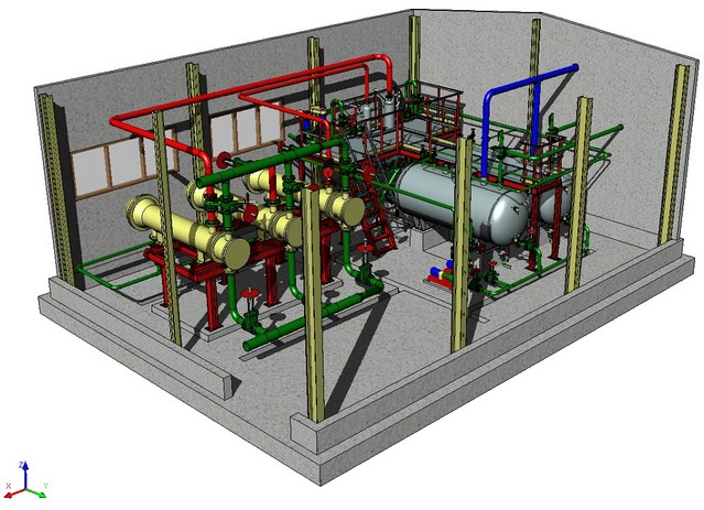
A capability is introduced for simple selection of the scene spinning center. Move the cursor to any object in the scene, depress the left mouse button and hold briefly, then the point under the cursor will be used as the spinning center until after the left mouse button is released. This is indicated by a cross-shaped marker displayed at the spinning center. After finishing spinning and upon releasing the mouse, the spinning center returns to its original position.
Changes in the Model Menu and Library Folders
The installed library configuration will load automatically after installation on the next T-FLEX CAD start. The «Open Library Configuration» command interface was modified. In case of installed but unloaded configuration the program will open the dialog box for configuration manual loading.
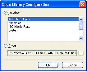
Document icons are now displayed in all modes of document menu windows. It is now possible to enable display of nested folders in the tool windows of folders and libraries (the context menu command "Show folders"). Therefore, it is now possible to use libraries with subfolders. When working with such libraries, the system uses relative paths to fragment files.
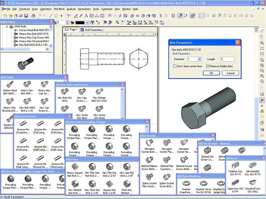
A library folder can be displayed as a custom-defined icon both in the "Model Menu" window and when working with the list of libraries. To have this, put a file named "library.ico" into the library folder. In this case, the icon image will appear automatically next to the library name.
Managing Document References
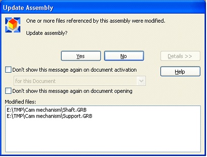
The mechanism of managing references from a document to other documents is improved. This mechanism is used by fragments, pictures, databases etc. The check of referenced documents being up-to-date now works faster and more accurately. When referenced files are changed, the system queries the user for updating references and displays the "Reference update" dialog. This dialog gained additional options, as well as the capability of viewing the list of files that were changed.
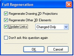
"Full 3D Model Regeneration" Command
This command gained the capability of simultaneously updating document references. An option specifies whether to update all or only the changed references.
●Importing Third-Party Document Formats
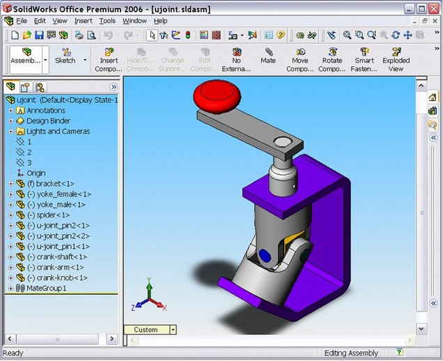
The system gained the capability of importing model files from SolidWorks and Solid Edge systems (command "Import"). When importing, it is possible to preserve the structure of assembly and mates. You can import either the files of individual parts or assembly documents. A relation is maintained with the original file; when the latter is changed, the model can be updated. To import SolidWorks files, you need to have an installation of SolidWorks 2004, 2005 or 2006 system on your computer. Import of Solid Edge files does not require Solid Edge installation.
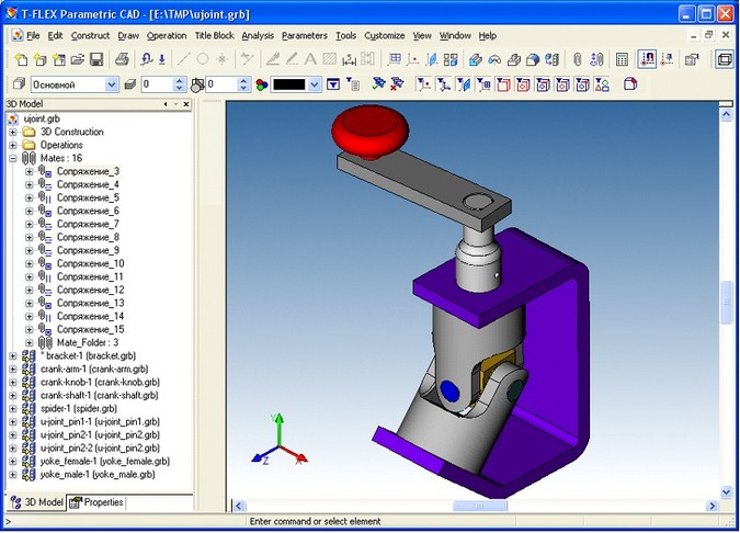
Zooming the Image by Spinning the Mouse Wheel
An option "Invert Mouse Wheel Direction on Zoom" is added on the "Preferences" tab of the "Options" dialog. It serves to switch to the opposite the zooming direction in the system windows as the mouse wheel is spun. This option may be convenient for the users who migrated from other systems.