Exploded View Scenario |
  
|
Exploded View Scenario |
|
The command is used for setting or editing exploded view parameters. You can perform the following steps in “Exploded view scenario” command:
●Create and edit exploded view scenarios. It is possible to create several exploded view scenarios.
●Create your own scenario of fragment exploded view as part of the general scenario.
●Define animation parameters.
●Control bodies visibility on each stage of exploded view scenario.
●Several exploded view scenarios can be created for an assembly. For example, assembly parts exploded view, assembly sequence, etc. Each scenario may consist of several stages. Stage includes sequence of actions. Action is an execution of individual transformation – translation or rotation of selected elements group. Group composition for various actions can be different.
To call the command:
Icon |
Ribbon |
|---|---|
|
Tools → Animation → Exploded View Scenario |
Keyboard |
Textual Menu |
<3TE> |
Tools > Exploded View Scenario |
Creation of Exploded View Scenario
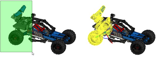
After activation you need to select objects which will be used for explosion view. For this purpose use options:
|
<O> |
Select object for individual transformation |
|
<1> |
Select objects for transformation |
When ![]() is selected it is possible to select only one object for transformation. You can select several elements using <Shift>.
is selected it is possible to select only one object for transformation. You can select several elements using <Shift>.
Upon selection of ![]() it is possible to simultaneously select several objects for transformation.
it is possible to simultaneously select several objects for transformation.
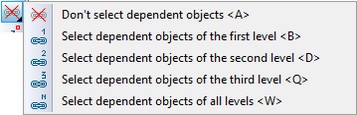
There is the possibility to choose dependent objects. For this purpose use special option in automenu:
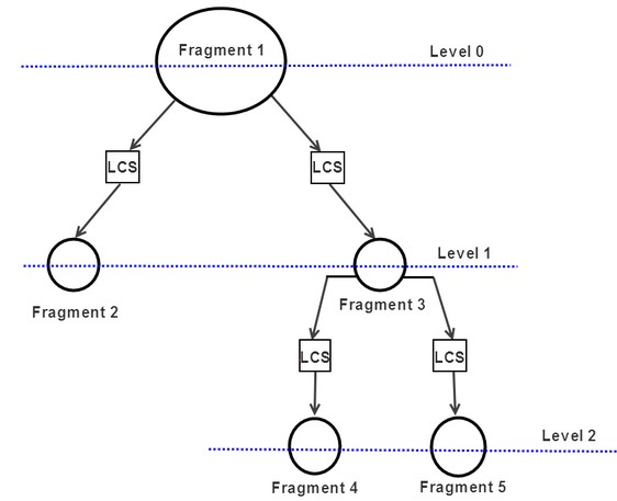
Levels of dependence mean hierarchical dependence of assembly elements. The zero level corresponds to the fragment that is selected in the assembly. The first level corresponds to all the fragments in the assembly that depends on the first one.
The option Don’t select dependent objects ![]() is active by default, that’s why only one fragment is selected in the scene.
is active by default, that’s why only one fragment is selected in the scene.
If you activate option Select dependent objects of the first level ![]() and select the same fragment, all the fragments that are directly dependent on the fragment will be selected.
and select the same fragment, all the fragments that are directly dependent on the fragment will be selected.
If you activate option Select dependent objects of the second level ![]() , the fragments dependent on the first level fragment will be also selected.
, the fragments dependent on the first level fragment will be also selected.
If you activate option Select dependent objects of all levels ![]() , all elements that directly or indirectly depends on the first selected fragment will be selected.
, all elements that directly or indirectly depends on the first selected fragment will be selected.
Using of the option is convenient in case of working with complex assemblies, for example, when you need to translate object together with its dependent objects.
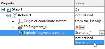
Creation of new or edition of existing explosion view scenario is made in the section [Scenario Selection].
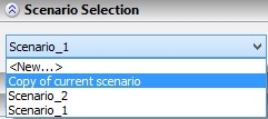
You can create a copy of an already existing script.
You cannot create a new script, if work with the current one is not finished.
The following objects can be selected as objects of the scenario: bodies, fragments, cameras, light sources.
To edit scenario properties use section [Properties].
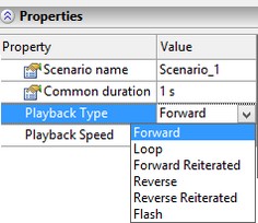
Using this section, you can edit name of scenario, set duration, type and speed of the exploded view animation.
Each scenario contains stages, divided into actions.
Full sequence of creating assembly from parts and subassemblies can be traced with the help of several stages.
For creating and editing stages of exploded view use [Contents] section.
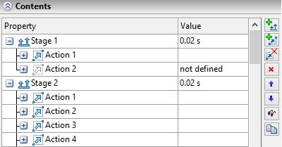
This dialog box contains information about created stages, actions, and objects, used in stages. Several graphical buttons are located to the right of the transformations list.
Button ![]() is used for creation of a new exploded view stage.
is used for creation of a new exploded view stage.
When you press ![]() button, a new action for selected stage is created.
button, a new action for selected stage is created.
Button ![]() is used to delete all transformations of a stage.
is used to delete all transformations of a stage.
Button ![]() deletes last exploded view stage in the list. To delete an action use button
deletes last exploded view stage in the list. To delete an action use button ![]() , located near actions name.
, located near actions name.
When you press ![]()
![]() buttons, the sequence of exploded view stages is changing. With the help of
buttons, the sequence of exploded view stages is changing. With the help of ![]() button, you can control stages visibility. When active, icon changes its color
button, you can control stages visibility. When active, icon changes its color ![]() . The “Hide” option affects not only the current stage, but also all following stages, until the activation of “Show” option. All bodies are visible by default.
. The “Hide” option affects not only the current stage, but also all following stages, until the activation of “Show” option. All bodies are visible by default.
There is a possibility to manage visibility and delete individual objects with the help of buttons. Hidden objects are shown in gray in the list.
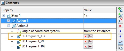
You can manage objects visibility only in current document.
Button ![]() allows to copy selected stage. The copied stage is added to the end of the list.
allows to copy selected stage. The copied stage is added to the end of the list.
Each action has one object or a group of objects and the chain of transformations for them. As a coordinate system for the chain of transformations you can use local coordinate system or coordinate system of the first group object (in a case of group transformations). A special option from automenu is used for the coordinate system selection:
|
<L> |
Select LCS for current transformation |
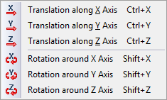
In case, when it is not possible right away to orient LCS in a desired way, the functions of additional coordinate system specification can be employed. These functions allow you to quickly rotate the constructed LCS around its axes by 90° (![]() ,
,![]() ,
,![]() ), perform cyclic turning of the axes of the coordinate system around the origin (when pressing
), perform cyclic turning of the axes of the coordinate system around the origin (when pressing ![]() the axes change their places).
the axes change their places).
All transformations are shown in the [Transformations] section of the properties window.
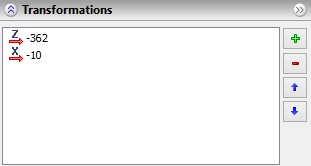
Several graphical buttons are located to the right of the transformations list. Button After type selection a new string appears in the transformations list. You can specify transformation value in the value input field. Transformation values can be assigned numerically or using variables and expressions. |
|
When pressing button ![]() the last transformation in the list is deleted. Pressing
the last transformation in the list is deleted. Pressing ![]()
![]() buttons changes sequence of transformations.
buttons changes sequence of transformations.
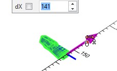
To save the transformations you need to press [Enter]. Also, a special manipulator in 3D window can be used to define transformations. This manipulator is moving according to the selected type of transformation.
Group transformation can be performed either in the “common” coordinate system, or in own coordinate system of each group member.
Mode of setting transformations in the common coordinate system is activated by default after selection of several objects for transformation:
|
<G> |
Set transformations of selected objects in common CS |
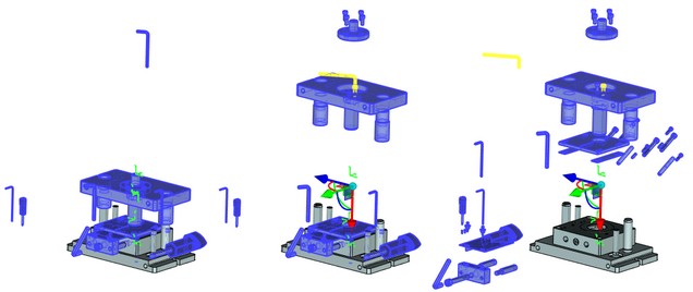
If this option is switched off, the group transformation is transferred into own coordinate system of each group member. I.e. when you move several fragments, each of them is moving along its own X axis.
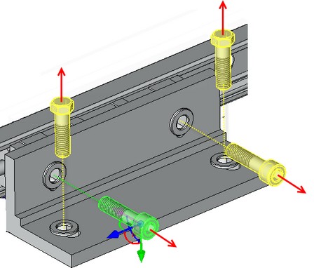
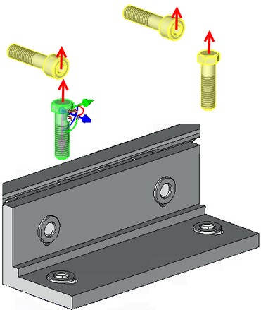
Each bolt is translated in its own coordinate system Bolts are moved in the common coordinate system
Thus, usage of the group transformations can significantly reduce time spent on specifying elements transformations.
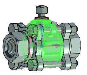
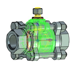
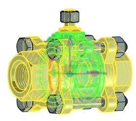
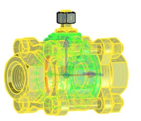
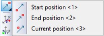
You can enable display of one of three positions: start, end and current, using options:
|
||
Start position |
Current position |
End position |
To improve convenience of objects selection use option:
|
<N> |
Group selection of objects by rectangle |
You can select rectangular area, holding ![]() . There are two selection conditions:
. There are two selection conditions:
1.All objects, which are completely covered by rectangular area, will be selected for the transformation. Common manipulator for these elements will appear. The cursor is moving from left to right.
2.All objects that intersect the rectangle will be selected. Common manipulator for these elements will appear. The cursor is moving from right to left.
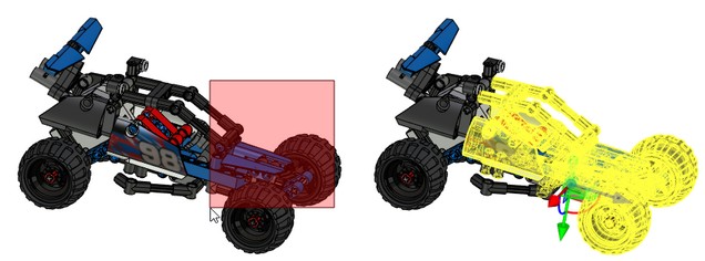
The area color differs for each condition.
Exploded View of Subassembly Elements
If there are subassemblies in the assembly you can move elements of the subassemblies separately. Use one of the following ways for this purpose:
If there is an exploded view scenario in the subassembly document, you can use it in the assembly. You need to select the subassembly fragment in the scene and choose one of its scenarios.
The second way to move subassembly elements separately is to divide subassembly using 3SD: Divide command. The way is not preferable, because the link between the product structure and subassembly is lost after division. This method can be used if the assembly document is used only for visualization.
Exploded view Animation
In “Exploded View Scenario” command, you can create animation of assembly/exploded view. While defining animation you specify position of assembly elements in each period.
The [Player] section in properties window is used to manage animation.
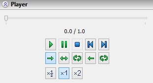
All elements movements are displayed on the time scale. Time scale represents horizontal line with slider. Slider indicates the playback time of current stage and total duration of animation. When you move the slider, current animation position changes and model is accordingly updated.
In the lower part of the section there are graphical buttons, which manage animation parameters.
![]() - Play. Starts animation.
- Play. Starts animation.
![]() - Pause. Temporary stops the animation at the current stage.
- Pause. Temporary stops the animation at the current stage.
![]() - Stop. Stops animation.
- Stop. Stops animation.
![]() - To Start. Scrolls animation to the beginning.
- To Start. Scrolls animation to the beginning.
![]() - To End. Scrolls animation to the end.
- To End. Scrolls animation to the end.
Animation starts in one of the following modes:
![]() - Forward Back. Plays the animation once from the beginning to the end.
- Forward Back. Plays the animation once from the beginning to the end.
![]() - Forward Reiterated Playback. Plays the animation in a circle (from the beginning to the end, from the beginning to the end, and so on) until the button
- Forward Reiterated Playback. Plays the animation in a circle (from the beginning to the end, from the beginning to the end, and so on) until the button ![]() is pressed.
is pressed.
![]() - Loop Playback. Plays the animation in a continuous cycle (from the beginning to the end, from the end to the beginning, and so on) until the button
- Loop Playback. Plays the animation in a continuous cycle (from the beginning to the end, from the end to the beginning, and so on) until the button ![]() is pressed.
is pressed.
![]() - Reverse Playback. Plays the animation once from the end to the beginning.
- Reverse Playback. Plays the animation once from the end to the beginning.
![]() - Reverse Reiterated Playback. Plays the animation in a circle (from the end to the beginning, from the end to the beginning and so on), until the button
- Reverse Reiterated Playback. Plays the animation in a circle (from the end to the beginning, from the end to the beginning and so on), until the button ![]() is pressed.
is pressed.
![]() - Normal playback speed. Playback speed set by default.
- Normal playback speed. Playback speed set by default.
![]() - Slow down playback. Playback with half speed.
- Slow down playback. Playback with half speed.
![]() - Speed up playback. Playback with double speed.
- Speed up playback. Playback with double speed.
The animation mode can be selected either before pressing [Play] button ![]() or while animation playback.
or while animation playback.
You can manage animation without activation of Exploded View Scenario command. For this purpose, the special tab on the Ribbon is used. It is called using the 3VX: Exploded View command.
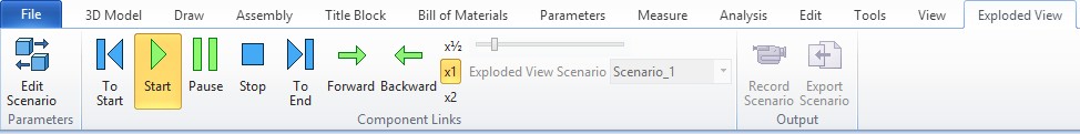
You can activate the command for scenario editing on the tab.
Main options for the exploded view playback are in the Control group. You can also select the scenario in the group.
You can stop animation by pressing<ESC>, model recalculation or reactivation of the Exploded View command.
In the Output group there are commands for record and export of the scenario.
Animation Record
The Record Scenario option allows animation recording in *.avi and *.wmv formats. General scenarios and scenarios by default are supported.
Record Scenario window appears when you select the option. Here you can set the following parameters:
You can select one of three variants in the Photorealistic view generation section.
Non-photorealistic rendering – the exploded view scenario is recorded according to the current view in 3D scene.
The following variants are used for photorealistic view creation. Each frame of the video is processed using selected photorealistic view mechanism.
Photorealistic rendering using OptiX – the video is created using NVIDIA OptiX mechanism.
Photorealistic rendering using Embree – the video is created using Embree mechanism.
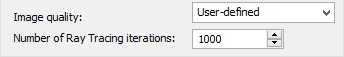
You can set Image quality and Number of Ray Tracing iterations for the previous two variants.
Photorealistic rendering using POV-Ray – the video is created u sing the POV-Ray mechanism.
You can find more information about photorealism in “Photorealistic view” chapter.
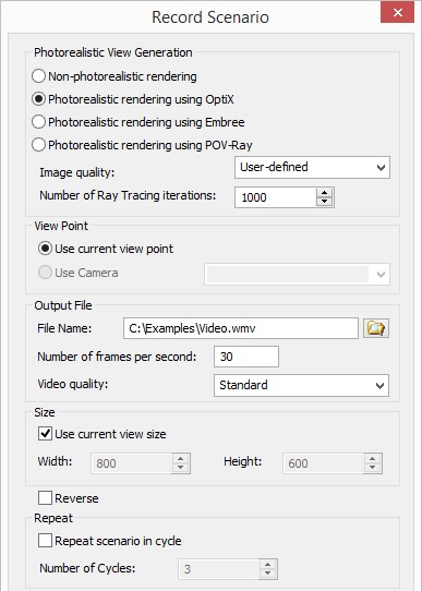
You can set view point using View point section.
●Use current view point. The video is recorded according to the current view point in 3D scene.
●Use camera. Video is recorded according to the selected camera from the list. It is available only if there are any cameras in the scene.
You can find more information about cameras in “Cameras” chapter.
You can set File name and Number of frames per second. The path to the created file is shown in the File name field. You can specify name, file path and file format using ![]() button.
button.
Video quality setting is available for the *.wmv format. The video quality and file size are changed according to its value.
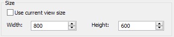
If the flag Use current view size is active, the video is recorded according to the active view size. Otherwise, you can set size manually.
The Reverse flag allows to record exploded view video in the reverse direction to the given in scenario.
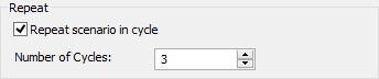
When the flag Repeat scenario in cycle is active, you can set Number of cycles. It sets number of exploded view scenario repeats.
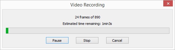
The Video recording window appears after the [OK] button pressing.
Number of processed frames and time until video creation are shown here.
Using buttons you can pause recording [Pause], stop record on current frame [Stop] or cancel recording [Cancel]. When you stop recording, already created part of the video is saved.
The preview window appears when you use photorealism.
●Save Scenario
Save scenario allows to export exploded view scenarios to *.wrl, *.x3d, *.pov, *.u3d, *.pdf formats.
The window Export Scenario appears after the command calling.
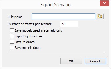
File path is displayed in the File Name field. You can select filename, its path and file format using button ![]() .
.
●You can specify Number of frames per second in the window. The scenario playback smoothness and file size depend on this parameter.
●Save models used in scenario only. All elements that are not used in the scenario will be not included in the file, when the flag is active.
●Export light sources. Light sources are included in the file.
●Save textures. The objects textures will be saved to the file. Otherwise they are not saved and the material of the object will be displayed instead of them.
●Save model edges. Model edges are saved when the flag is set. The flag is enabled only for *.wrl and *.x3d formats.