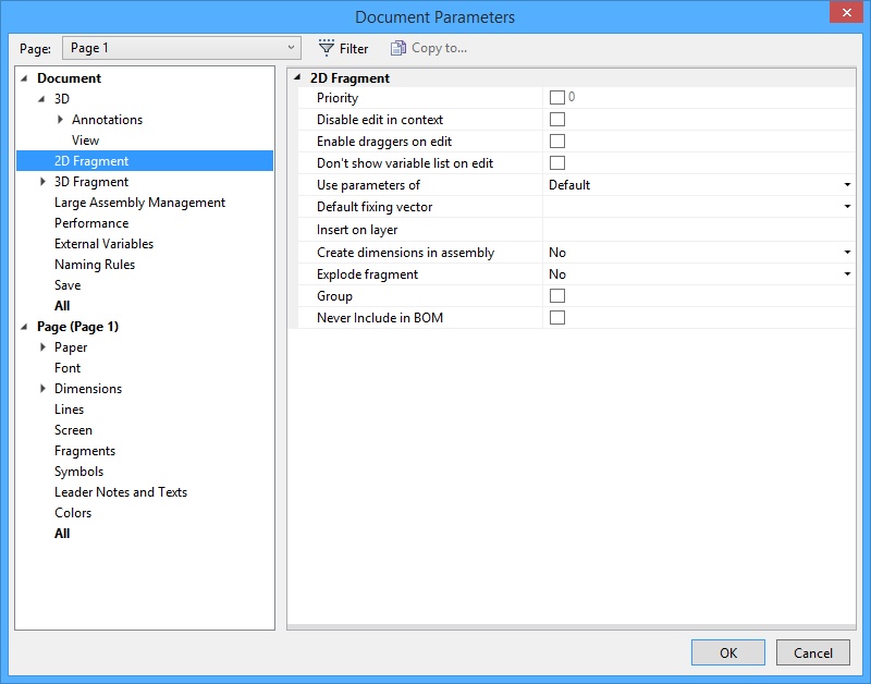
On 2D Fragment tab you can define the fragment attributes on inserting the document as a fragment.

Priority. Setting this attribute allows to define a priority value to be assigned to the fragment on inserting into an assembly drawing.
Disable Edit In Context. When set, editing this document in the assembly context is prohibited.
Enable Draggers on Edit. If set, the draggers will be enabled for this assembled 2D fragment in the fragment editing mode. The draggers allow modifying the external variables of the fragment by using the mouse.
Don’t show Variables List on Edit. This option hides “Preview” and “Variables List” flags in the fragment parameters dialog box on editing. The option works only for the custom dialog boxes of fragment variables.
Use Parameters of. This parameter allows specifying what settings of the drawing will be used upon inserting the given document into the assembly as a fragment:
Default. The default settings specified in the assembly for the parameters of the 2D fragment will be used;
Fragment Document. The settings of the current document will be used;
Current Document. The settings of the assembly drawing will be used.
Default Fixing Vector. This parameter sets the main fixing vector used upon insertion of the given document as a 2D fragment. This parameter duplicates the corresponding flag in the properties of the fixing vector.
Insert on layer. This parameter specifies the name of the layer on which a 2D fragment will be placed when the given document is inserted into the assembly.
Create dimensions in assembly. Option is used to insert dimensions existing in 2D fragment into an assembly. When 2D fragment with dimensions is inserted into the assembly drawing, the dimensions are transformed to separate elements as if they were created right in the assembly drawing. There are three options:
No. Dimensions that already exist in fragment file will be included into assembly. Such dimensions can’t be edited because they are part of the fragment.
Automatically. Dimensions will be automatically created after the fragment insertion. When 2D fragment with dimensions is inserted into the assembly drawing, the dimensions are transformed to separate elements as if they were created right in the assembly drawing. These dimensions will not be inserted from the fragment file; they will be created directly in the assembly document. The dimensions will be created according to the dimensions from the fragment file, i.e. their locations and attachments will be inherited from the fragment. You can edit the dimensions. The dimensions will be correctly displayed if you rotate fragment using fixing vector.
The dimensions will be created only if they are based on graphic lines. Dimensions based on construction lines or nodes will not be created.
If the dimension is considered to be driving in the fragment file, i.e. it’s nominal size is set by an external variable, you can change the variable value in the assembly. The fragment and its dimensions will be recalculated according to the new value.
Manually. After fragment insertion, its dimensions won’t be created in the assembly. To add dimensions into the assembly you need to use Create dimensions in assembly command in the fragment context menu.
![]()
The dimensions will be created in the same way as for Automatically.
Explode fragment. Allows to explode 2D fragment when it is inserted into an assembly. The fragment is deleted after explosion and all its visible elements copies will be created in the assembly.
No. The fragment won’t be exploded after insertion.
Without construction. Only copies of all visible graphic elements from source document will be created.
With construction. Copies of all visible graphic and construction elements from source document will be created.
Group. All fragment elements will be automatically grouped after fragment explosion.
The option is used only for exploded elements.
Never include in BOM –fragment data is not included into product structure, when the flag is set.