Array Classes |
  
|
Array Classes |
|
Array classes. Specifics of each class of arrays
All 3D arrays created in T-FLEX CAD can be distinguished by the way of copying into the following classes:
● Linear;
● Circular;
● By Points;
● By Path;
● Parametric.
Linear array
The linear array is created by placing copies of the source objects along one or two direction vectors. Depending on the number of the direction vectors, it will be either one-dimensional or two-dimensional array. All elements of the linear array lie in one plane.
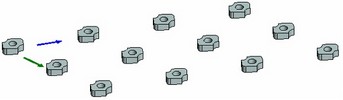
The direction vectors of a linear array are defined either by two 3D points (in this way, the vector will be directed from the first selected point to the second one), or by a single 3D object suitable for defining a vector in the space.
The array size along each direction is characterized by the number of copies, the placement step and the total length of the array in the given direction. To define an array, you need to specify just two of the three parameters. Depending on the mode used, it can be:
● Number of copies and step;
● Total length and step;
● Number of copies and total length.
In any of the modes, one of the specified parameters (the array step or the total length in the given direction) can be automatically calculated by the system based on the length of the direction vector and the value of the other parameter.
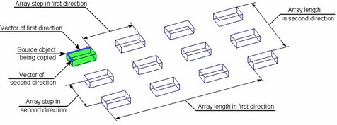
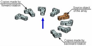
The number of copies along each direction vector always includes the source object being copied (even if it is not included in the composition of the array). For example, the array shown on the above diagram contains 4 copies in the first direction and 3 copies in the second direction.
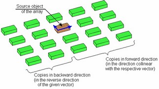
A linear array allows creating copies not only forward, but also backward along each direction vector. The backward copies are created with the same step as the forward-going copies along the given vector. The number of copies in the backward direction can either be the same as in the forward direction along this vector, or specified by a separate numerical value.
Circular array
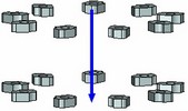
In the circular array, the copies are placed on a circle about the array axis. The axis of revolution of a circular array is defined, just as the direction vectors in a linear array, by selecting two 3D points or one 3D element suitable for defining a vector in the space.
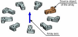
The position of array elements about the axis is determined by the number of copies, the rotational step per copy and the total angle of elements rotation about the axis. The copy rotational step determines, by what angle to rotate the source body about the axis to place the first copy. The second copy is created by rotating the first one by the same angle, and so on. The rotation is done in the clockwise direction, as watched along the array axis.
Backward rotation is possible, including simultaneous creation of copies in two directions – forward and backward. The backward rotation is done with the same step as the forward one, while the number of copies may differ.
To define an array, you need to specify two defining parameters out of the three, for example:
● Number of copies and step;
● Total angle and step;
● Number of copies and total angle.
The third parameter is calculated by the system automatically.
The rotation step or the total angle of the arrayed elements can be defined by two additional 3D points. The sought angle will be equal to the angle between the planes passing through the rotation axis and the respective 3D point.
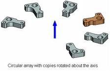
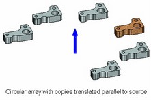
When copies are created, there are two possibilities for a copy's orientation: rotated and parallel-translated. In the first case, a copy is created by actually rotating the source body about the array axis. In the second case, the source body is copied without rotation about the axis (meaning that orientation of each copy in the space is the same as the source body orientation).
The circular array also allows creating copies in the second direction: in the radial direction of the array. In this case, array elements will be located in one plane, making up a pattern of concentric circles. Alternatively, the second direction can be chosen along the axis, with the array elements put on a cylinder.
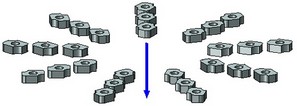
The number of copies along the second direction is specified in the same way as in the linear array.
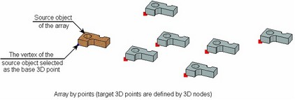
Array by points
To create a 3D array by points, select the base 3D point on the array's source object, and an arbitrary number of target 3D points (into which the source object will be copied). The arrayed elements will be placed in the specified 3D points.
The target points are defined with successive selection of single 3D points (3D nodes, vertices, etc.) or arrays of 3D nodes. The list of target points of an array may contain both 3D points and arrays of 3D nodes.
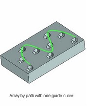
Array by path
In the array by path, the placement of the array elements is defined by one or two 3D curves. Such an array can be considered analogous to the linear array, however, with the copies placed along one or two spatial curves rather than straight lines. Those curves can be represented by arbitrary 3D curves (3D paths, 3D profiles, curvilinear edges, etc.). If a closed 3D curve is selected, you need to additionally specify a 3D point, whose projection on the selected curve would determine the start of the array curve.
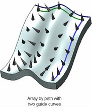
Use of a single guide curve results in a one-dimensional array, two guide curves – in a two-dimensional array by path. For simplicity, let's first review creation of an array by one guide curve.
The placement of copies (array elements) along the guide curve depends on the following array parameters: number of copies, step and total length of the array along the given curve, and, additionally, the copies' placement option.
Number of copies, step and total array length along the guide curve are interrelated parameters. To define the array, you need to specify just two parameters out of the three. The omitted parameter will be calculated by the system automatically. The total array length can be evaluated by the guide curve (the system will determine the curve length, and then take the resulting value as the length of the array in the given direction).
The total array length may not exceed the length of the guide curve.
The placement option determines:
- The position of the copies' placement points (array elements) along the guide curve. Depending on the used placement option, the step of the array by path determines either the distance along the path between the fixing points of the copies or the path's chord length.
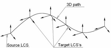
- The orientation of copies in the space. The position of copies in the space is determined by bringing the target coordinate system of each copy over the source coordinate system of the object being copied (that case, the source object of the array). The source coordinate system is created at the start of the guide curve, while the target – at the fixing point of the particular copy. The axis orientation of either coordinate system is defined by the copy placement option.
There are the following copy placement options:
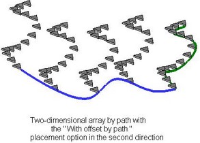
With offset by path. The target coordinate systems of all copies are placed along the path according to the specified step and "number of copies" parameters. The axis orientation of those coordinate systems is fixed and does not depend on the 3D path geometry. This placement option can be used, if you need to put copies of the source body along the guide curve, preserving the spatial orientation of each copy as that of the source body. |
|
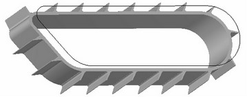
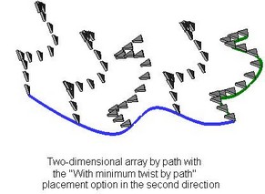
With minimum twist by path. The X-axis of the target coordinate system of each copy is determined as to provide smooth rotation of the curvature vector from the start to the end of the path. The Z-axis always points in the direction tangent to the path at the origin of the current copy's coordinate system. An example using an array by path with minimum twist by path as a model of a conveyor belt. |
|
This example can be found in the library "Examples", in the folder "\3D Modeling\Arrays \Conveyor.grb".
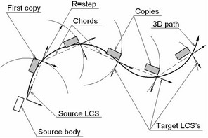
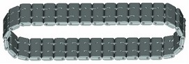
By span. To find the position of the first copy, a sphere is created with the center at the path start and the radius equal to the array step. The copy will be placed at the intersection point of the sphere and the 3D path. Next, another sphere is constructed with the center at this point, and so on. This is how attachment points of all copies are determined. The target coordinate systems of the copies are placed in those points. The X-axis of a target coordinate system is oriented by the incoming chord of the 3D path. A path chord is defined by the attachment points of two neighboring copies. The source coordinate system is located at the start of the path. Its X-axis points toward the first copy's position. With this copy placement option, the array step is the chord length of the 3D path. This placement option can be successfully implemented, for example, in caterpillar belt and chain drive design. |
|
A caterpillar belt design example is provided in the library "Examples", in the folder "\3D Modeling\Arrays \Track.grb".
The two-dimensional array by path is created similarly. The set of parameters is defined for the second guide curve in the same way, including the step and total length of the array in that direction and the copy placement option. Note that the source object in the second direction will be the complete set created by the one-dimensional array along the first guide curve.
Parametric array
The parametric array uses a universal approach that allows creating an array by parametric copying of the source element. The same approach is used in the "By Parameters" operation and in one of the 3D path creation modes. The algorithm of face approach is described in details in the "By Parameters" chapter. Therefore, the current topic just briefly touches upon the algorithm description and the typical examples.
A parametric array can be an array of bodies, operations or construction elements only. Parametric arrays of faces cannot be created.
To create a parametric array, you need to define the law of calculating the so-called coordinate system of the current copy. The copying of the array source object is done in the direction from the source coordinate system to the calculated target coordinate system of the current copy.
The user can select one of the model's local coordinate systems as the source coordinates. If no local coordinate system was selected, then the global coordinate system is used as the source coordinates.
The coordinate system of the current copy (particularly, its origin and axis orientation) can be defined in one of the two ways:
●Free copy orientation. Modifications of the coordinate system parameters of the current copy are described by expressions.
●Copy orientation by 3D curves or surfaces. To define the spatial position of the current copy's coordinate system, use the appropriate 3D curves or surfaces of other bodies. By managing the copy's coordinate system, you control the position of each copy.
The position of a copy's coordinate system is controlled by the array parameters. All parameters are divided into two types - driven parameters and driving parameters.
Driven parameters are the parameters whose values are calculated automatically during element creation. One can introduce independent variables to read the values of such parameters.
Driving parameters are the entries whose values are specified by the user. The entries for the driving variables permit arbitrary expressions including any system variable. For example, including a variable keeping the copy ID number, in such an expression, will make the given parameter depend on the copy ID.
Some array parameters can be sometimes driving, and sometimes driven. The leading parameter "Number of copy" is always driven. It definitely requires assignment of an independent variable that will be tracking the current copy ID number during the operation processing. The copy number is automatically incremented through the array calculation, starting from 1, up to the specified quantity, with the step equal to 1.
The calculation is done in the following order: the copy number is assigned the next ordinal number, then the driving parameters are calculated, then the driven parameters are calculated (if any), and, finally, copying is done.
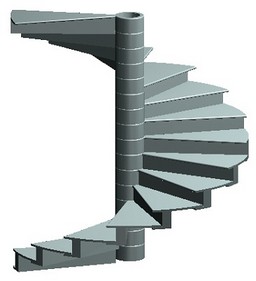
When using the free copy orientation option, just select the array source object, specify the number of copies and assign independent variable to the "Number of copy" parameter. By using the variable assuming the current copy number, one can introduce certain relations in the entries of driving parameters, as well as in 2D or 3D constructions, and make the geometry of the original body, in turn, depend on those relations.
An example of a parametric array with free copy orientation is a model of a spiral staircase, as shown on the diagram at the beginning of this topic.
The copy orientation option by path or by surface is convenient in the cases when defining the expression for the exact law of the copy parameters modification is not feasible. In such cases, it is convenient to use various 3D curves or surfaces for specifying the position and orientation of the current copy's coordinate system.