Limitations and Exclusions |
  
|
Limitations and Exclusions |
|
Limitations and exclusions are used to exclude some of the created copies from an array.
Limitations
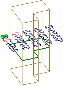
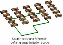
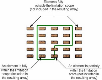
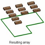
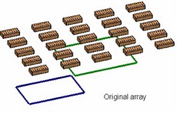
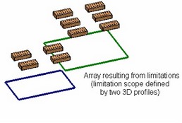
Setting a limitation means defining a subset of the 3D space to which copies creation is limited – limitation scope. When in this mode, all copies that are created per the main array parameters are checked by the system for falling in the limitation scope. If a copy fully falls within the scope, it will be included in the resulting array. If a copy is located outside the limitation scope or fits in but partially, it is not included in the resulting array.
Limitations may not be available with all classes of construction element arrays, and are not available with any parametric arrays.
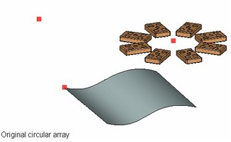
The limitation scope is defined by a 3D object with sheet geometry – a face, 3D profile or a sheet body. The selected object is swept from both sides along the limitation axis for the infinite distance. The resulting swept area will be the limitation scope of the array.
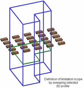
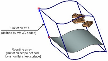
If the limitation scope is defined by a flat 3D object, then the limitation axis coincides, by default, with the normal of the selected object's plane. If necessary, you can specify an arbitrary direction of the limitation axis by defining the axis directions by two 3D nodes or one 3D object suitable for defining a straight line. In the cases when the array limitation scope is described by a non-flat sheet 3D object, the limitation axis must be explicitly specified.
The limitation scope can also be defined by multiple sheet 3D objects. All objects are swept in the same direction. The limitation scope will be the sum of the scopes swept by each of the selected object.
Exclusions
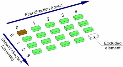
Exclusions, or excluded elements are the array elements that shall not be included in the resulting array. Any array elements can be excluded, except the source object.
Exclusions can be defined for the following array classes: linear, circular and array by path.
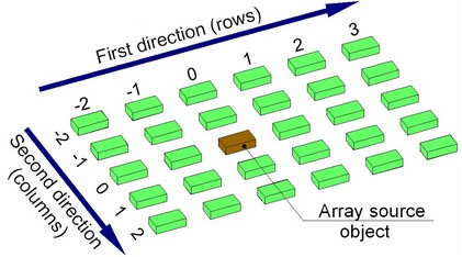
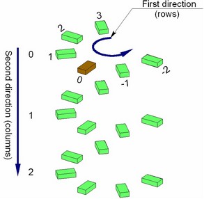
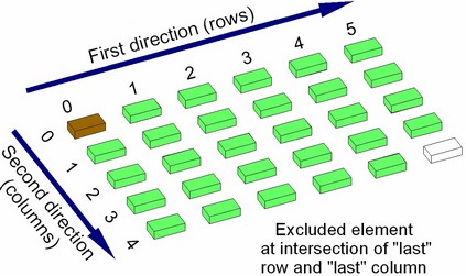
An exclusion is specified by its position in the original array, that is, the column and the row in the array, at whose intersection this element is located (in the cases of the circular array and array by path – generalized "row" and "column"). The dimension of the array in the first direction defines the number of rows, in the second the number of the array columns.
Rows and columns in arrays are numbered as follows:
- 0, 1, 2, …, N-1 – in the forward direction (N is the number of copies in a row/column in the forward direction)
- -1, -2, …, -M+1 – in the backward direction (M is the number of copies in a row/column in the backward direction).
Note that the column and the row numbers, in which the source object of the array is located, are 0. This is important when defining exclusions.
You cannot exclude the array element with the coordinates (0,0) from the array of Bodies.
Instead of the number of particular rows/columns, one can use descriptive characteristics defining their position in the original array:
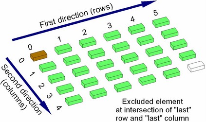
- Starting row/column is the row/column in which the source object of the array is located (the number 0);
- Last row/column is the row/column, which is the last in the forward direction of array creation;
- Last in Opposite Direction row/column is the row/column, which is the last in the backward direction of array creation;
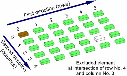
This way of specifying exclusion locations is convenient for removing elements of the outer rows/columns from the arrays of variable size, especially when the array dimensions are defined by the total length and the step, or the total length and the number of elements. Suppose, for example, that you need to exclude an element in a linear array of size 5x4, that is located at the intersection of the last row and the last column of the array (assuming that the copies are created in the forward direction only along both vectors). One can simply specify the element at the intersection of the row number 4 and column number 3 as the element to exclude. However, should the array grow (for example, to 6 rows and 5 columns), the excluded element will have the same exact coordinates (the last row will be now number 5, and the column – number 4). Instead, to have specifically the last element of the array always excluded, the exclusion should specify the element at the intersection of "the last" row and "the last" column.
Each specified exclusion can be subjected to the following additional options:
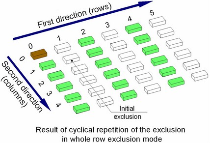
● Whole row exclusion. Use of this option causes exclusion of the whole row with the specified element from the array;
● Whole column exclusion. With this option, the column with the specified element is excluded from the array;
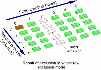
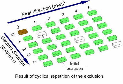
● Cyclical Iteration. The result of applying this option depends on whether the previous options are used. If those are not used, then use of this option will cause deletion of not only the original exclusion, but also the elements following it after the same number of rows and columns from the start of the array. If this option is used together with the previous ones, the whole cyclically repeating rows or columns will be excluded.
Modifying number of copies in array. Referencing array elements
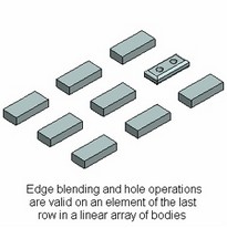
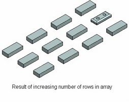
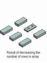
When the number of copies of any array changes, then additions or deletions of elements occur immediately before the last array copy in the given direction. The IDs of geometrical components in the elements of the outmost array rows and columns do not change through such additions or deletions (outmost are the first and the last elements in any direction).
Therefore, any operation created on an element of the first or the last row (the first or the last column) of the array stays intact through any changes in the array dimensions. For example, an edge blend created on an element of the last row in an array of Bodies or operations, will regenerate correctly, regardless of increases or decreases in the number of rows in the array.
Operations created on "inner" copies of the array could run into regeneration errors, as the array dimension is decreased.
Defining limitations
To specify a 3D element defining the limitation scope, activate the following option in the command automenu:
![]() <Alt+C> Select limiting elements
<Alt+C> Select limiting elements
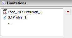
3D elements are selected in the 3D scene by clicking ![]() . 3D profiles and operations can also be selected in the 3D model tree. The selected objects are put in the list of limiting objects in the section "Limitations" of the operation properties window. To cancel selection of some of the specified objects, click those in the list of the limiting objects and press the button
. 3D profiles and operations can also be selected in the 3D model tree. The selected objects are put in the list of limiting objects in the section "Limitations" of the operation properties window. To cancel selection of some of the specified objects, click those in the list of the limiting objects and press the button ![]() .
.
To start defining limitations, you can simply focus on the respective entry of the operation properties window. The option for specifying the limiting objects will be activated automatically. If a flat 3D object was selected, the limitation scope will be hinted in the 3D scene as a sweep along the normal direction of the selected object. If non-flat the limiting objects are specified, the limitation scope will be created only upon specifying the limitation axis. To define the limitation axis by a single 3D object, use the option:
To define the axis by the start and end points, use the options:
|
|
To reject selection of the limitation axis, use the option:
![]() <Alt+K> Cancel selection of auxiliary direction of limits
<Alt+K> Cancel selection of auxiliary direction of limits
Defining exclusions
To specify the array elements to be excluded, activate the following automenu option:
![]() <ALT+X> Select elements to Exclude
<ALT+X> Select elements to Exclude
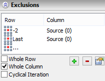
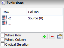
To select an element to be excluded, just click its preview image in the 3D scene by the ![]() . The selected element will be highlighted Gray in the 3D scene and added to the list of elements to exclude in the "Exclusions" section of the properties window. The list of excluded elements is made into a table that displays the numbers of the rows and columns of the selected exclusions. To remove an exclusion from the list, pick it in the list and press the button
. The selected element will be highlighted Gray in the 3D scene and added to the list of elements to exclude in the "Exclusions" section of the properties window. The list of excluded elements is made into a table that displays the numbers of the rows and columns of the selected exclusions. To remove an exclusion from the list, pick it in the list and press the button ![]() .
.
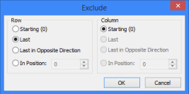
The position of the elements specified by selecting in the 3D scene, is entered in the table using numerical notations for the row and the column. The button ![]() allows defining an exclusion by using descriptive characteristics of its position. Upon pressing the button, a dialog box appears for specifying an element to exclude.
allows defining an exclusion by using descriptive characteristics of its position. Upon pressing the button, a dialog box appears for specifying an element to exclude.
In this dialog, specify, at intersection of which row and column lies the element to exclude, by setting the "Row" and "Column" switches in the desired states. Besides the descriptive characteristics, you can also use here they numerical notations of rows and columns. To do this, select the "In Position" choice and enter the number of the row/column. Upon closing the dialog box by pressing the [OK] button, the specified exclusion will appear in the list of the elements to exclude.
To use the mode of excluding a row/column in the mode of cyclical repetitions for one of the specified exclusions, select it in the list of the elements to be excluded in the properties window and set a flag for it, representing the desired mode:
- "Whole row" – sets the row exclusion;
- "Whole column" – sets the whole column exclusion;
- "Cyclical Iteration" – sets cyclical repetitions of the exclusion.