Large Assembly Management Tools |
  
|
Large Assembly Management Tools |
|
To optimize working with assembly models, the system provides specialized large assembly management tools. Those allow working only with the subassemblies of concern, save the overall used memory and facilitate spinning the 3D scene when it is densely populated with objects. A “large assembly” is a model in which the large assembly mode is activated.
The large assembly mode is activated in the ST: Set Document Parameters command on the Large Assembly Management tab using Unload Body Geometry Automatically parameter:
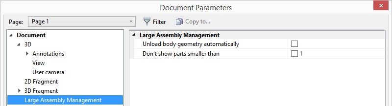
This mode is turned on automatically. It depends on the model complexity and the computer resource availability.
First of all, the large assembly mode provisions for freeing memory by automatically unloading the detailed information about the assembly objects. Such bodies are displayed seemingly normal, however their edges, vertices, faces, etc. cannot be selected.
Such parts are highlighted in a special color when selected and are marked in the model tree with a special icon (“feather”). The omitted data is loaded automatically as needed.
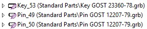
Such a need arises when editing parts, when performing various modifications and geometry analysis, as well as when creating projections.
You can also specify mimimal size of displayed parts.
The image detailing level can be set for 3D fragments. One can choose a “Rough”, “Middle” or “Accurate” quality.
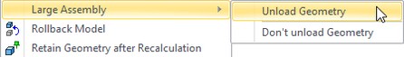
When in the large assembly mode, the context menu on selected parts gains special commands that serve to:
●Unload Geometry. Force unloading Body geometry from the assembly;
●Load Geometry. Force loading Body geometry to the assembly;
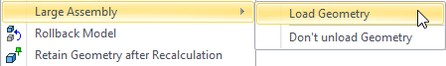
●Don’t unload Geometry. When this option is active, the geometry of the concerned body will not be unloaded automatically.
An auxiliary means that helps ease working with large assemblies is the capability of creating 2D projections based on a 3D model located in an external file. This allows separating the model handling process and the drawing creation. An associative relation is still maintained between the drawing and the model.