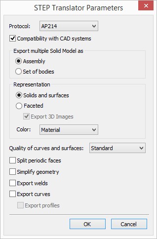
If STEP export format was selected, the “STEP translator parameters” dialog appears after entering the file name. Here you can specify the process options.
Protocol provides compatibility of STEP files with older versions of CAD systems. New protocol is enabled by default. Older protocol version AP203 doesn’t support colors, so the Color option is unavailable for it.
Compatibility with CAD systems option provides possibility to read STEP file in other CAD systems.

Export multiple Solid Model as group:
Sets the mode of exporting a multiple-solid model:
Assembly. The model being exported is converted as an assembly with its hierarchy.
Set of Bodies. Geometry contained in the file being converted is exported as a plain set of bodies without creating an assembly structure. Each body contained in the model is exported separately.
Representation specifies type of bodies export: boundary representation based on geometry (Solids and surfaces) or faceted polygonal representation (Faceted).
Export 3D Images option is available for mesh representation. If it is disabled, objects of 3D image type will not be exported into STEP file.
Color option specifies source of bodies color: basic material color or shading color.
Quality of curves and surfaces. Setting this option forces conversion of all non-analytical surfaces into B-spline surfaces. Accuracy of current geometry conversion into representation spline can be set using the drop-down list. The geometry is converted only if it is necessary. This might improve the resulting export in some systems, as, for example, in CATIA and SolidWorks, but increases the size of the resulting file. It is recommended to use standard quality by default.
Split periodic faces defines the method of converting periodic geometry present in the model.
By periodic geometry, we mean cylindrical, toroidal, spherical surfaces and their counterpart spline surfaces. When converting a model into the STEP format, such surfaces and curves can be broken into pieces for better export results.
Simplify geometry option removes excess topology from the model and reduces file size. It is disabled by default, as export time and memory consumption grow when it is used.
Export welds. When the option is enabled, welds are exported. Welds are transformed into bodies.
Export curves. When this parameter is set on, in addition to bodies of the model, the wire geometry will be exported as well.
Export profiles. When the flag is set, profiles are exported.
Curves and profiles are transformed into paths.
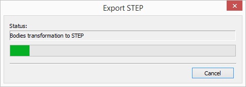
Convertation process is performed after pressing [Ok] button. The progress bar follows on the overall conversion process.
