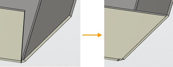
Corner


Corner |
  
|
There is a special operation SMC: Corner for setting corner parameters at sheet bodies:
Icon |
Ribbon |
|---|---|
|
Sheet Metal → Corner |
Keyboard |
Textual Menu |
<SMC> |
Operation > Sheet Metal > Corner |
The operation enables users to create relief at untreated corners of sheet parts and create overlapping.

The operation requires selecting an adjacent folds intersection vertex. When choosing the vertex special markers appear.
●Overlapping marker, consisting of two parts: an icon of selecting the overlapping type and an icon of gap value. The overlapping types are switched successively by pressing ![]() on the overlapping icon.
on the overlapping icon.
|
|
|
Overlap |
Without overlap |
Reverse overlap |
When pressing ![]() on the gap value icon there appears an entry field.
on the gap value icon there appears an entry field.

●Corner relief marker, representing an icon depicting relief type.
|
|
|
|
Round |
Square |
Welding |
No |
Weakening types are switched successively by pressing ![]() on the icon.
on the icon.
Overlapping type, gap value and relief type can be set in the operation dialog.
Command parameters
Following general sheet material parameters are available for the command:
●Bend Relief (corner). With choosing between four variants from the list: Round, Square, Welding and No (if no relief is required).
●Gap type. With choosing between three variants from the list: Without overlap, Overlap and Reverse overlap.
●Gap.
When choosing Corner command corner treatment is done automatically.

Command automenu options are:
|
<Ctrl+Enter> |
Finish input |
|
<P> |
Set entity Parameters |
|
<X> |
Exit command |
|
<F5> |
Preview Operation Result |
|
<V> |
Select Vertex |
|
<A> |
Select Bend |
Finish input. Builds a geometry according to the given parameters. In case there are not enough parameters set, the option is not available.
Set entity Parameters. Calls a standard dialog of 3D modeling command parameters.
Exit command. Shuts down the command with cancelling all the set parameters.
Preview Operation Result. Enables/disables the standard option of 3D modeling commands review.
Select Vertex. Enables users to choose the corner to be edited. The option is active at calling the command. It is necessary to select the adjacent elements folds intersection vertex.
Select Bend. Alternative option of selecting the corner. Requires selecting adjacent elements folds.
Corner creation
A typical procedure when creating a corner is:
●To select a folds intersection vertex.
●To set general corner treatment parameters: Bend Relief, Gap type, Gap.
●Finish entering.