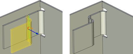
Jog


Jog |
  
|
To build a jog at sheet bodies SMJ: Jog operation is used:
Icon |
Ribbon |
|---|---|
|
Sheet Metal → Jog |
Keyboard |
Textual Menu |
<SMJ> |
Operation > Sheet Metal > Jog |
The operation enables users to create a double fold at a sheet body at a random angle. Jogs can be helpful when it is necessary to build overlapping flanges, increase sheet part structure rigidity or provide a gap between two flanges.

The length and position of the flange built at the second fold is determined by the initial face: the flange is parallel to the initial face and its length corresponds to the projection onto the initial face.
Command parameters
Command parameters are general for sheet metal commands and are described in the corresponding subsection above.
The command automenu options are:
|
<Ctrl+Enter> |
Finish input |
|
<P> |
Set entity Parameters |
|
<X> |
Exit command |
|
<F5> |
Preview Operation Result |
|
<L> |
Select Line |
|
<E> |
Select first Vertex or 3D Node |
|
<S> |
Select second Vertex or 3D Node |
|
<W> |
Draw Profile |
|
<D> |
Reverse side |
|
<F> |
Select Face |
Finish input. Builds a geometry according to the given parameters. In case there are not enough parameters set, the option is not available.
Set entity Parameters. Calls a standard dialog of 3D modeling command parameters.
Exit command. Shuts down the command with cancelling all the set parameters.
Preview Operation Result. Enables/disables the standard option of 3D modeling commands review.
Select Line. Selects a straight line determining the base bending line of the first fold. The line can be set basing on the path, profile or the trace. The line should be a segment lying entirely within the face limits (or the segment projection onto the face should lie within the face – in case the segment does not belong the face).
Select first Vertex or 3D Node. Chooses the first point determining the base bending line.
Select second Vertex or 3D Node. Chooses the second point determining the base bending line.
Draw Profile. Sets the base bending line of the first fold in transparent mode. When choosing the option you should set the workpiece face (the system automatically switches to drawing at the selected work plane mode), after which you should create a segment at the selected face. The segment should connect opposite face edges or lie within the workpiece face. When exiting the drawing at the selected work plane mode the profile created will be selected automatically.
Reverse side. Jog creates two parallel faces, one of which coincides with the initial one staying stationary by default. This option swaps the stationary and moving faces.
Select Face. Selects the face which the operation is applied to. By default the nearest one to the set bending line is selected.
Creating a jog
A typical procedure when creating a jog is:
●To select a rectilinear profile lying within the workpiece face or connecting opposite workpiece face edges.
●Set general bending operations parameters: Height (Length in other operations), Angle etc.
●Finish entering.