Reference Element


Reference Element |
  
|
The command allows you to create a top-down relationship, between an assembly and a fragment, or between fragments, through geometry borrowed by a fragment from an assembly, or one fragment from another fragment.
Icon |
Ribbon |
|---|---|
|
Assembly → Assembly → Reference Element |
Keyboard |
Textual Menu |
<3RE> |
|
Main chapters
Updating of Reference Elements
Automatic Creation of Reference Elements
Reference Element in Geometric Parameters
Eliminating Recursions Using Reference Elements
The reference element in the fragment is an element, which constructions tree is not available. The constructions tree of the source geometry of the reference element is in another fragment file. This file will be called a geometry source file (Geometry Source). Reference Elements allow you to borrow three-dimensional objects geometry to perform subsequent operations on the edited assembly fragment. The basic elements of the model (3D nodes, coordinate systems, workplanes, 3D profiles, 3D paths, bodies of various types), and topological elements (edges, faces, vertexes) can be borrowed.
As mentioned above, a reference element should be created only in the context of the assembly (except when you want to create an internal reference to eliminate recursion).
To create a reference element, you should call fragment editing in the context of the assembly (see "Working in context of assembly"). Call the <3RE> Reference Element command. Select any available assembly element or group of elements. In the "Model Elements" window, you can see the created elements list. To expand the list of reference elements, click the icon next to the field indicating the number of reference elements.

In the "Reference Parameters" tab you can add a reference element after or before the current one with the help of icons ![]() and
and ![]() correspondingly. Using the icon
correspondingly. Using the icon ![]() , you can delete the selected reference element, using the icon
, you can delete the selected reference element, using the icon ![]() you can delete all selected elements.
you can delete all selected elements.
When you create a reference element, you should specify:
●Is it required or not to update the geometry in the recalculation (see section "Updating of reference element");
●Is it required or not to create geometric adaptive parameters (for more information, see “Reference element in geometric parameters");
●The source of the geometry, that is, specify how to update the reference element (for more information, see "Geometry source").

Complete the creation of the reference element using the icon ![]() or <Ctrl+Enter>.
or <Ctrl+Enter>.
The reference element always has the source geometry located outside of the fragment (except for internal references, eliminating the recursion). Reference elements cannot change their geometry, they can only borrow geometry, according to a reference to another file that contains the source geometry. The source geometry can be changed in the file where it is located, then the reference element needs to be updated. It borrows a new variation of the source geometry.
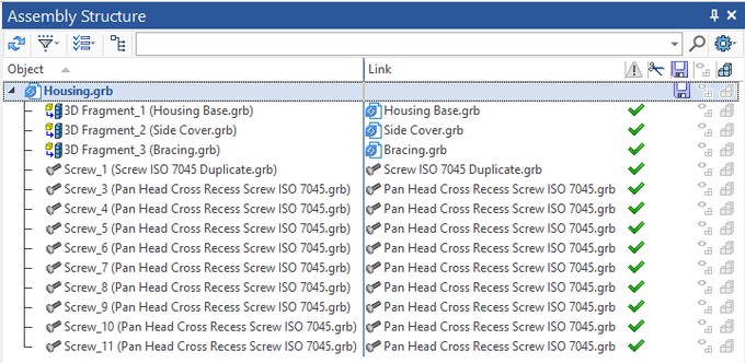
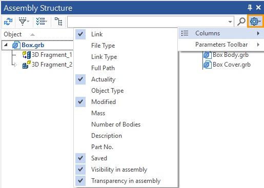
Reference elements of the fragment can be seen in the "Assembly Structure" window. The name of the geometry to the reference element, the name of the file which contains the source geometry and the file name of the source document settings (Get Parameters from the Documents) are shown in the "Reference Elements" tab. In this case, the transformation parameters are meant (you can read more in the section "Positioning, scaling and variation of fragments in assembly"). The parameter source file is always the assembly in the context of which the reference elements of the fragment were created. The source geometry file (Geometry Source) you choose when you create a reference element.

You can see the reference elements of the fragment in the "3D model" window of the assembly. If the assembly is a file that contains the source geometry, you can also see the source geometry of the reference element in the "3D model" window.

A reference element can be seen in the "3D model" window of the fragment.

Updating of Reference Elements
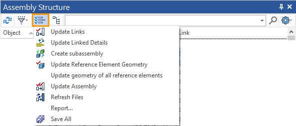
You can update reference elements from the "Assembly Structure" window of an assembly, or from a subassembly, and only the reference elements that are included in that subassembly will be updated. You can update the reference elements of all the fragments in the assembly (subassembly).

You can also update the reference elements of a specific fragment. To do this, select the fragment and select the command shown in the figure.
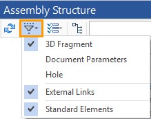
You can update one specific reference element only in the "3D model" window of the fragment file that contains the reference element by calling the Update Geometry command in the context menu of the reference element.
You can update reference elements through the "Assembly Structure" window only if the reference element does not have an option: Do not update geometry when recalculating. If the option is active for the reference element, the reference element need to be updated independently. You should use the Update the Geometry command in the context menu of the reference element in the "3D model" of the fragment file containing the reference element.

When creating a reference element, you may or may not specify the Do not update geometry when recalculating option. By default this option is not active. When automatically creating reference elements using the Detail > Create command, the option is not active.
By default, all reference elements (except internal references) are created with the ability to update when recalculating.
The Do not update geometry when recalculating option is available in the parameters of the reference element when it is created.

If you activate the option, the reference element will be fixed and can only be updated manually via the context menu of the reference element in the "3D model" window.
In the 3D model window of the fragment file, you can find out whether its reference element is fixed or not. The fixed elements have a different icon (with a picture of a pushbutton), and the Do not update geometry when recalculating option is active in the context menu.
The reference element is fixed: ●the icon has a pushbutton; ●the Do not update geometry when recalculating option is active. This reference element can only be updated manually. |
|
Reference element is not fixed: ●The icon is normal, without pushbutton; ●The Do not update geometry when recalculating option is not active. This reference element can be updated through the "Assembly Structure" window. |
|
In order to determine which file will contain the source geometry of the reference element, you need to specify one of three options:
●Assembly,
●Fragment of first level,
●Initial fragment.

The Fragment of first level is set by default.
If you specify not set when you select a file that contains the source geometry of the reference element, the selected element in the context of the assembly will be used upon the fragment construction, but will be fixed and cannot be updated.
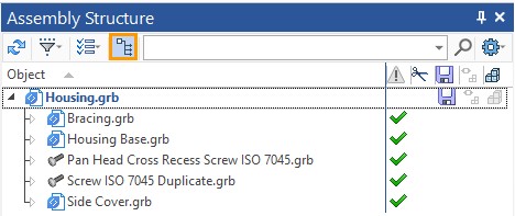
As mentioned above, a reference element can only be created in the context of an assembly. To do this, open the assembly file, and then through the "Assembly Structure" window open the fragment for editing (for more details, see "Working in context of assembly"). In the "Assembly Structure" window, we see only those fragments that are included in the assembly. The entire structure above (if we opened the subassembly file) will not be visible to us, neither in the scene nor in the "Assembly Structure" window, and do not affect the creation of reference element.
In this case, we mean the current hierarchy of fragments, which determines which file on the disk should be accessed in the future to find the source geometry of the reference element. This option is valid only once, when creating a reference element. If the file containing the source geometry has a different hierarchy in the final assembly, the system will find it. If the file is deleted, the link will not be updated, because the source geometry will not be found.
Assume that the source geometry to which a reference element refers upon update was specified in the assembly. No geometry is created directly in the assembly, all geometry in the assembly is determined by the fragments that are included in it. This means that in order for the source geometry of the reference element to be available in the assembly, it must contain the fragment in which the source geometry is located. Therefore, if you remove a fragment from the assembly, the source geometry will not be found by the reference element when you update.
The edit panel in the context of the assembly (upper right corner of the 3D scene) duplicates the option to specify the selection of the file containing the geometry source. |
|
You should carefully monitor this option when automatically creating reference elements in the context of an assembly.
Automatic Creation of Reference Elements
Reference elements will be created automatically in two cases.
●If you edit a fragment in the context of an assembly with the enabled selection of assembly elements ![]() (Select assembly Elements), and an assembly element was used during execution of any command.
(Select assembly Elements), and an assembly element was used during execution of any command.
●If we use the Detail > Create command for the body in the assembly.
When automatically creating reference elements, the Do not update geometry when recalculating option is not active.
All auto-generated reference elements (except auto-generated internal links to eliminate recursion) will be updated during recalculation.
If necessary, you can disable the update of the created reference element. To do this, in the context menu of the reference element (called in the "3D model" of the fragment file) you need to specify the flag of the Do not update geometry when recalculating option.
When you use the Detail > Create command on a body in an assembly, reference elements will be created for those constructions that cannot be moved to the created fragment file.
If there are elements among the parent elements of a body that depend on other bodies, such parent elements cannot be taken from the assembly. In this case, a reference element is created.
For example, a profile is built on the face of the body, which is the parent of the body that we want to save to a separate file. This profile cannot be taken from an assembly without the body on which it is built. But we do not need the second body in the created file. Then a reference element will be automatically created for the profile. In the created file, the specified profile will be a reference element.
Reference Element in Geometric Parameters
The presence of a reference element in the geometric parameters allows you to change the geometry in the assembly without updating the reference elements in the fragment files to obtain a new execution of the adaptive fragment. In this case, the reference element will behave as an external variable: the execution of the fragment in the assembly does not depend on the execution of the file fragment. Reference elements in geometric parameters allow you to create adaptive assemblies. If the assembly has fragments of the second level and below, it is possible to create a chain of adaptive fragments, as it was shown in the subsection "Create detail using Detail > Create command".
The presence of reference elements in the geometric parameters of the fragment is shown in the "Assembly Structure" window.

The reference element will be placed by default in the geometric parameters of the fragment if you create it in the context of the subassembly for which the fragment is a fragment of the first level (you should specify the geometry source in the assembly Geometry Source: assembly), while the subassembly itself, for a general assembly, can be a fragment of any level. If the reference element is placed in the geometric parameters of the fragment, then, when you change the geometry, the source of the reference element, the adaptive fragment will change its geometry, according to the change of the source geometry, but only in the assembly. At the same time, there will be no changes in the fragment file where the reference element is located. To change the geometry inside the fragment file, you should update the reference element according to the change in the source geometry.
The reference element will be in the geometric parameters of the fragment if it is created in the following ways.
●Using the <3RE> Reference Element command. The fragment for which the reference element is created should be opened in the context of the assembly for which the fragment is a level 1 fragment, and the Geometry Source: assembly , and the Create geometric adaptive parameters options should be specified.
●When editing a fragment of the first level in the context of an assembly with the automatic creation of reference elements (when the option ![]() is active and you use the assembly elements in the fragment constructions), the Geometry Source: Assembly and the Create geometric adaptive parameters options should be selected.
is active and you use the assembly elements in the fragment constructions), the Geometry Source: Assembly and the Create geometric adaptive parameters options should be selected.

●The reference element is created automatically when you run the Detail > Create command with the Create Adaptive Fragment option.
You can cancel the creation of geometric adaptive parameters based on the reference element.
To do this, disable the Create geometric adaptive parameters option flag in the Reference element command parameters when creating a reference.

Control of the Create geometric adaptive parameters option is duplicated by the icon in the panel available when working in the context of the assembly (upper right corner of the 3D scene).
![]()
If the icon ![]() is active - the created reference elements will be placed in the geometric parameters of the fragment (in the case when a source is an assembly ). IF the icon
is active - the created reference elements will be placed in the geometric parameters of the fragment (in the case when a source is an assembly ). IF the icon ![]() is disabled, they will not be placed.
is disabled, they will not be placed.
You should carefully check this icon when automatically creating reference elements in the context of an assembly. In some cases, the adaptability of the fragments may lead to recursion.
More information about recursions and their elimination can be found in the subsection below.
In the case of recursion, you can remove the reference elements from the geometric parameters. To do this, call the context menu of the adaptive fragment and select ![]() Edit. Next, in the "Geometric parameters" tab, remove the reference element from the geometric parameters using the icon
Edit. Next, in the "Geometric parameters" tab, remove the reference element from the geometric parameters using the icon ![]() or remove all the geometric parameters using the icon
or remove all the geometric parameters using the icon ![]() .
.

The derived object (derived from object) allows you to transfer the geometry directly from a fragment at any level to the assembly file. The basic elements of the model (3D nodes, coordinate systems, workplanes, 3D profiles, 3D paths, bodies of various types), and geometric elements (edges, faces, vertexes) can become derived elements.
The derived element transfers the geometry from bottom to top. Therefore, all the principles of working with assemblies on the "Bottom-up" principle are valid for the derived element.
If we change the geometry in the fragment, including the geometry referenced by the assembly, and then save the fragment, the geometry of the derived element will be updated when the assembly is updated.
In General, an analogy can be drawn between a reference element and a derived one. A reference element provides a "Top-down" relationship (and a link between fragments), a derived element provides a "Bottom-up" relationship. But since the principles of updating the reference elements and derived elements are still different, you should not confuse them.
Derived object is similar to external element (External) by the principle of operation. You need to transfer sequentially on all levels from subassembly to subassembly only the external element, and the derived element can be transferred to assembly at once.
In an assembly, the derived element will be an element whose constructions tree is not available.
Derived Element Creation
The command for deriving an element is available in the context menu of any element (listed above). To derive an element from a fragment to an assembly (or subassembly), you should first open the assembly (or subassembly) file. There are two ways to select the desired fragment element to derive it into the required assembly.
●Open a fragment in the context of an assembly, then open the context menu of the element by selecting it in the 3D scene or in the "3D model" window and specifying Derive to assembly.
|
|
●In the 3D model window of the assembly file, expand the fragment constructions, find the required element and use its context menu to call the Derive to assembly command.

In the assembly file, we can see the derived elements. For an assembly, it will be a reference element, so the elements derived from the fragment, in the assembly file, are in the "Reference elements" folder. For a fragment, these are derived elements. In the "3D model" window of the assembly file, you can find a list of the derived elements in the corresponding folder of the fragment from which you derived the elements.
Automatic Creation of Derived Element
Automatic creation of derived elements is possible when we use the command Detail > Create and create a fragment (both adaptive and non-adaptive).
If there are parent elements of other bodies among the child elements of a body (which you want to keep in a separate fragment) then such elements cannot simply be taken from the assembly. In this case, the Derived Object is created. Derived Object will depend on the fragment and will define the geometry of the dependent bodies in the assembly.
For example, on a face of a body (which we want to save as a fragment), a profile is created, which is the parent of another body. This profile will be saved with the body to a fragment file. To ensure that the body dependent on the profile does not lose the parent element, a derived element will be created. The derived element will return the profile that is saved in the fragment file, to the assembly.
Eliminating Recursions Using Reference Elements
Upon creating adaptive fragments (the Detail > Create command the Create Adaptive Fragment option) may be a recursion if the constructions "pulled" from the assembly depends on each other. Let's explain this with a simple example.
Let's say you have two boxes. Construct circle profiles on one of the faces of each of the boxes. It turns out that one profile is a child of the first box, and the second is a child of the second.

Extrude the profiles, and then subtract the resulting cylinders from parallelepipeds using Boolean operation. You should subtract the cylinder, created by the extrusion profile, which belongs to the first box, from the second box. And the cylinder, created on the profile of the second parallelepiped (box) should be subtracted from the first box. As a result, it turns out that each of the parallelepipeds has another parallelepiped as its parent and its child.
Call the context menu for the first parallelepiped and choose the command Detail > Create. In the command dialog, specify the Create Adaptive Fragment option.

Click "OK". A dialog box with a message about recursion appears.
Four variants of recursion elimination are proposed.
1) Do not create adaptive parameters. That is, it is proposed not to place reference elements in geometric parameters. Reference elements, unlike geometric parameters, are themselves recursive. Recalculation of fragment begins with updates of the borrowed geometry, then the rest of the constructions tree of the fragment is recalculated. After the fragment is recalculated, the changes appears in the Assembly. Changes in the geometry of a fragment causes a change in the source geometry of the reference element of the fragment in an assembly, . But this change will only be passed to the fragment the next time it is recalculated. This eliminates looping recalculations on themselves.
In this case, the fragment will be non-adaptive.
2) Break recursion in assembly element. In this case, an internal reference to the profile will be created inside the assembly file, the parent of which is the body in the assembly (the second parallelepiped). Therefore, for a fragment reference element, the source geometry will not be a profile in the assembly, but an internal reference to that profile in the assembly. Since the source geometry, for the internal reference, which is the source geometry for the reference element of the fragment, is in the assembly, the method itself is called "Break recursion in assembly". An internal reference that is updated only manually breaks the recursion. Since the reference is not updated when recalculating, the geometry of the reference element is fixed, and does not depend on the change of the parent element, and there is no recursion when recalculating the geometry of the adaptive fragments. For the body of the second parallelepiped, a reference element is also created. The source geometry of the reference element is the profile of the first parallelepiped derived from the fragment. For the first parallelepiped such element is called derived.
The fragment will be adaptive in this case: there will be a reference element in its geometric parameters.
|
|
The internal reference that breaks the recursion is updated only manually. You cannot update it from the "Assembly Structure" window.
You can find out that the internal link is fixed and is not automatically updated by its icon with the image of a pushbutton button. To update a link, open its context menu and select Update geometry.
3) Break recursion in reference element. In this case, an internal reference to the reference element will be created inside the assembly file. The source geometry of the reference element is the profile of the fragment of the first parallelepiped. For the fragment, such element is called derived. Since the source geometry of the reference element to which the internal reference is created, is in the fragment, the method itself is called "Break recursion in detail". An internal reference that is updated only manually breaks the recursion. At the same time, the fragment itself also has a reference element. The source geometry for the reference element is a profile, whose parent element is the second parallelepiped. The body of the parallelepiped is in the assembly.
As in the previous version of the recursion elimination, the created fragment will be adaptive: there will be a reference element in its geometric parameters.
|
|
4) Add depended object to the detail. In this case, the generated fragment will contain both bodies and will be non-adaptive (an assembly unit will be created).
The user himself can eliminate recursions with the help of internal reference elements. To create an internal reference element, you need to call the <3RE> Reference Element command while in the edited file (not in the context of any assembly) and select the model element from the 3D scene or model tree in the "3D model" window.
See also: Top-down Assembly Design