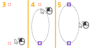
Construction Ellipse through Two Nodes, Using Axis Length |
  
|
1. Call the ![]() Ellipse command.
Ellipse command.
2. Make sure that the following automenu option is active:
|
<T> |
Select Node of Ellipse |
3. Select a first 2D node for the ellipse to pass through. A node may be selected in one of the following ways:
•Press ![]() or <Enter>, while the cursor is within drawing window, in order to select a node nearest to the cursor.
or <Enter>, while the cursor is within drawing window, in order to select a node nearest to the cursor.
•Move the cursor over an intersection of construction lines or a characteristic point of a graphic line, using object snappings, and press ![]() or <Enter>. A connected 2D node will be created automatically at the specified point.
or <Enter>. A connected 2D node will be created automatically at the specified point.
•Activate the following automenu option:
|
<N> |
Select Node |
If the option is activated via keyboard, then the node nearest to cursor gets selected instantly.
If the option is activated via mouse, then you have to additionally press ![]() within drawing window for selecting the nearest node.
within drawing window for selecting the nearest node.
4. Select a second 2D node for the ellipse to pass through. The first axis of the ellipse will connect such node with the node selected on the previous step. A node may be selected in one of the ways described above.
5. Specify the length of ellipse's second semi-axis in one of the following ways:
•Type a length value or a name of a variable via keyboard into the input box of the parameters window. Then press <Enter> or click ![]() anywhere within drawing window for finishing the input.
anywhere within drawing window for finishing the input.
•Place the cursor at an arbitrary point of drawing window without snapping to existing elements and then press ![]() or <Enter>. The length of ellipse's second semi-axis will be calculated so, that it ensures passing of the ellipse through such point.
or <Enter>. The length of ellipse's second semi-axis will be calculated so, that it ensures passing of the ellipse through such point.
Regardless of the way of definition, length of the second semi-axis is saved in ellipse parameters and can be edited later.
During second semi-axis length definition, the preview of the ellipse follows the cursor within the area limited by the length of the first semi-axis. When the cursor is outside this area, the preview is not displayed and arbitrary point cannot be specified.


After creating an ellipse the command returns to the initial state.